-
• Main Page
- • Home
• Antennas - • 10.1 MHz
- • 14 MHz
- YBN 14-5wzsA compact class 28 ohms, 13 m boom 14 MHz 5 ele. straight split Dipole to be very uncritical for home building. A wideband version with hugh bandwidth and yet high F/B.
Elevation Plot
- YBN 14-5w rmcA full size 50 ohms, 15.4 m long 14 MHz 5 ele. with straight split Dipole to be very uncritical for home building. The Yagi covers the full 20 m band with a VSWR < 1:1.1
Elevation Plot
- YBN 14-5wzs
- • 18.1 MHz
- • 21 MHz
- • 24.9 MHz
- YBN 12m-4wA 4.7 m long 24.9 MHz 4 ele. Yagi with straight split Dipole to be very uncritical for home building.
Elevation Plot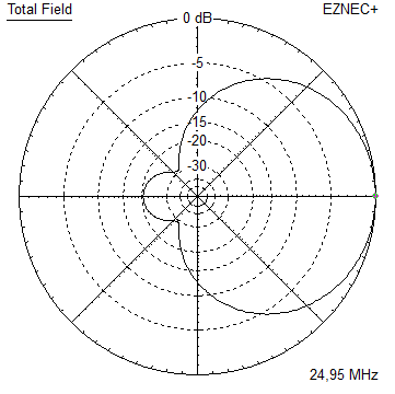
- YBN 12m-5nA 8.6 m long 24.9 MHz 5 ele. Yagi with straight split Dipole to be very uncritical for home building.
Elevation Plot
- GTV 12m-3mA 3.7 m long 24.9 MHz 3 ele. Yagi with with bent Dipole.
Elevation Plot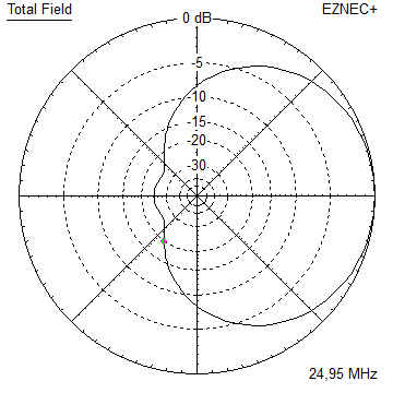
- YBN 12m-4w
- • 28 MHz
- • 50 MHz
- • 70 MHz

YBN 14-5wzs with Conventional Driven Element
"Compact class 5 el. Yagi covering the 20 m band"
The YBN 14-5wzs is a 28 ohms, short boom wideband beam covering the full 20 m band. Short boom means 13 meters. Which actually is short in wavelengths for a 5 element Yagi. Design date of issue: 2018.12.21
wzs = wide, non 50 ohms, short boom
Performance Data
Specs: with 40 mm elements @ 14.2 MHz
Gain vs. isotr. Rad.   9.9 dBi
Gain vs. Dipole        7.8 dBD
-3 dB E-plane         55.2 deg.
-3 dB H-plane         74.2 deg.
F/B                  -24.3 dB
F/R                  -17.0 dB
Impedance               28 ohms
VSWR Band Width       14.0 MHz = 1.15:1, 14.35 = 1.16:1
Mechan. Length        13,000 mm exclusive boom offsets for elem. plates
Electr. Length        0.616 λ

Stacking Dist. h-pol.
top-to-bottom        17.5 m or 57.4 ft
side-by-side         22.8 m or 74.7 ft
How many HF operators have been looking up this design since Dec. 2018?
Geometry
... is available in request
Pattern and VSWR Plots
Elevation and Azimuth plot at 14.2 MHz

RL and SWR plots - simulated
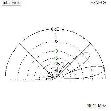
Tapered Model Azimuth plot 14.0 - 14.35 MHz
14.10 MHz F/B = 20.34 dB Gain = 9.89 dBi
14.20 MHz F/B = 23.55 dB Gain = 9.89 dBi
14.35 MHz F/B = 28.75 dB Gain = 9.87 dBi
Pattern and VSWR Plots over Ground
Azimuth plot at 14.2 MHz at height of 18 m (perfect gnd assumed)

VSWR plot at 14.2 MHz at height of 18 m (perfect gnd assumed)
Note: fine tuned > DE plus 15 mm per side = 2 x 5300 mm, D1 plus 10 mm per side = 2 x 5105 mm
Validation of Tapering
Tapered Yagi:
73, Hartmut, DG7YBN