YBN RS-8wz wideband 28 ohms Yagi for reception of Radio Sondes
Wideband version with SWR < 1:1.3 from 400 to 406 MHz
This Yagi is designed to meet expectations for easy building but clean pattern for the necessary bandwidth for
monitoring the complete 400 - 406 MHz Radio Sonde band. It is 28 ohms feed, the known widely as 'DK7ZB match'
with two parallel 1/4 λ coax cables provides a easy match to 50 ohms. A ferrite core added on the matching line
is welcome but not essential.
This design is developed using the YBN 2-8m 144 MHz Low Noise Yagi as baseline. No other then DK7ZB himself
converted my design to 28 ohms by modifying its driver cell; see here
This 'double destilled' design is what I scaled to 403 MHz now.
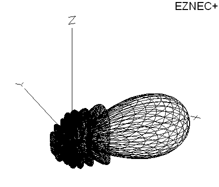
Current distribution

Performance Data
                       402 MHz        403 MHz       404 MHZ
Gain vs. isotr. Rad.  13.1 dBi       13.1 dBi      13.2 dBi
Gain vs. Dipole       11.0 dBD       11.0 dBD      11.0 dBD
-3 dB E-plane                        41.4 deg.
-3 dB H-plane                        47.2 deg.
F/B                  -33.6 dB       -29.6 dB      -26.9 dB
F/R                  -22.3 dB       -22.0 dB      -21.6 dB
Impedance                              28 ohms
Mechan. Length                       1246 mm
Electr. Length                       1.67 λ

Stacking Dist. h-pol.
top-to-bottom                        0.93 m
side-by-side                         1.05 m
Geometry
With ø 8 mm elements


4 and 8 mm Element Tables
       Refl.    DE       D1       D2       D3       D4       D5       D6
Pos.   0        121.5    181.0    306.0    516.0    761.5    1019.0   1246.0
Lgth.  364.0    340.4    337.0    331.0    322.5    315.5    311.0    301.1      4 mm without BC
Lgth.  360.0    340.0    328.0    321.0    311.0    303.0    299.0    289.0      8 mm without BC
Lgth.  367.1    347.1*   335.1    328.1    318.1    310.1    306.1    296.1      8 mm with BC = 7.1 mm for on 20 x 20 Boom
4 mm elements insulated through boom BC:Use DJ9BV BC numbers and nylon rivets on square boom as shown on BC-page
8 mm elements On-Boom:
Use DG7YBN BC numbers and standard insulators (Nuxcom, WiMo, Konni) on square boom as shown on BC-page
As this Yagi is designed using a low segmentation density there is no SBC to be applied.
just add common Boom Correction.
Mind ... this is UHF. Cut elements very precisely. Use a large calliper gauge if you can get one. Make a mark
for final length, saw about 0,5 mm in front of the mark and grind down to final measure. Below you find BC numbers for
other boom dimension
Elements through boom - Suggestion how to build with no offset between dipole and elements

Element cutting table with numbers derived using SM5BSZ's BC.exe applied to 4 mm model and proposed insulators (s. below)
Ø_outer = 6 mm, Ø_inner = 4 mm, boom tubes wall thickness = 2 mm on 20 x 20 square boom.
One might add 120 .. 200 mm on rear boom end as offset for all ele. positions and produce a formast mounted Yagi.

Sketch of the YBN RS-8 with 4mm elements through boom

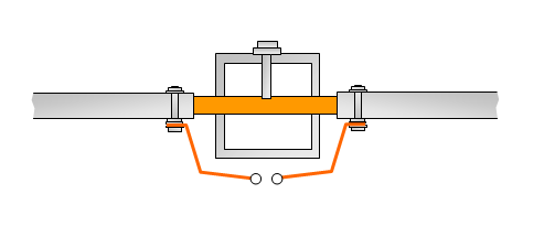
Feeding the dipole, using copper wire, side screws M3 and a solid plastic intersection

The dipol might be subject to length adjustment here in order to compensate for the copper
wire connections from aluminuim tubes to coax.
Insulators - self drilled furniture bore hole covering plugs

In Dubus 4/2014 I show details about the SM5BSZ BC for mounting elements through boom adapted
to 432 MHz and this particular style using furniture bore hole end plugs in detail.
The "Yagi Element Configuration Tool" has this SM5BSZ BC added since release V1.32 .
How came to visit this website?
Pattern and VSWR Plots
Elevation and Azimuth plot at 432.1 MHz (horizontally polarised - for vertical polarisation swap views)


SWR plots - full band

Downloads
EZNEC file of this Yagi with 4 mm elements
EZNEC file of this Yagi with 8 mm elements
73, Hartmut, DG7YBN


