

Performance Data and Geometry
Pattern and VSWR
Download as File
Stacking
A Review on the 8 Element DK7ZB "OWM" Yagi
When DK7ZB announced to turn to "focus on the noise figure" and "develope some models with these fundamentals" I guess
that others were excited just like me what he would come up with. Being widely known for good designs we owe him full attention
when he introduces a new technique. So, when I noticed that DK7ZB published what he derived at using my "5-8" as baseline
I wanted to see how good it is and if I could do even better with 28 ohms now. Meeting my own skills according the 8 OWL's
wave guiding structure it was not that easy, but I grinded of some Kelvins finally without losing but gaining some bandwidth.
In this case I think it is quite legitmately to add a bit of fine tuning to a design that goes back on my ideas and is shown
off as "Low Noise" and wide band, though DK7ZB did not publish Antenna Temperature or G/T yet. Scroll down to "Stacking"
and find Antenna Temps and G/T numbers comparative to the VE7BQH G/T Table with the exception that I used approximately same very
high segmentation density that DK7ZB is known for (>30) to be on level with the 8 ele. OWL. Hence numbers given might vary by
one or two 10th depending on the chosen segmentation density. But that does not alter the basic directions shown.
Current distributions
| Original "5-8" 50 ohms | DK7ZB 8 ele. 28 ohms OWM | Fine tuned 8 ele. 28 ohms |

|

|

|
Element positions
		Refl	DE	D1	D2	D3	D4	D5	D6
DG7YBN 5-8	0	282	403	822	1440	2130	2850	3485
DK7ZB 8 OWL	0	340	505	855	1440	2130	2850	3485
Performance Data of fine tuned 8 ele. 28 ohms version
Gain vs. isotr. Rad.  13.15 dBi
Gain vs. Dipole       11.00 dBD
-3 dB H-plane         41.2  deg.
-3 dB E-plane         47.0  deg.
F/B                  -27.82 dB
F/R                  -22.08 dB
Impedance                28 ohms
Mechan. Length         3485 mm
Electr. Length         1.68 λ

Stacking Dist. h-pol. (DL6WU)
top-to-bottom         2.609 m
side-by-side          2.957 m
Geometry

Note: element lengths for Ø 8 mm fit 5/16" too

Use EZNEC's Auto-Segmentation at 600 MHz and correct elem. lengths
by 2.x mm  plus for real builds due to very high segmentation base
Pattern and VSWR Plots
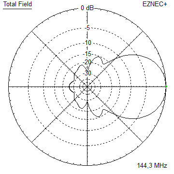
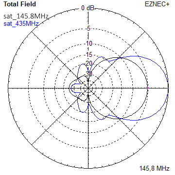
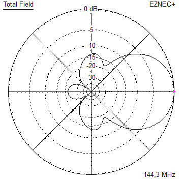
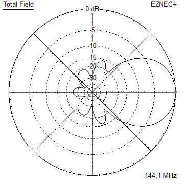
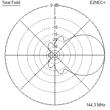
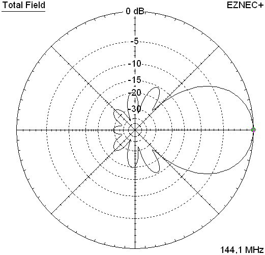
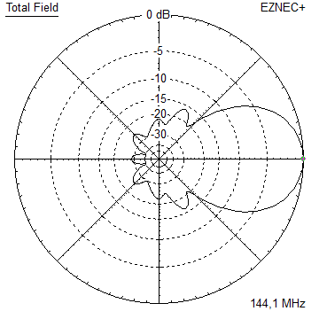
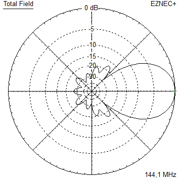
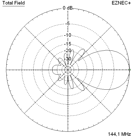
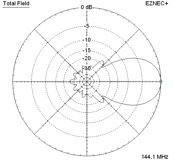
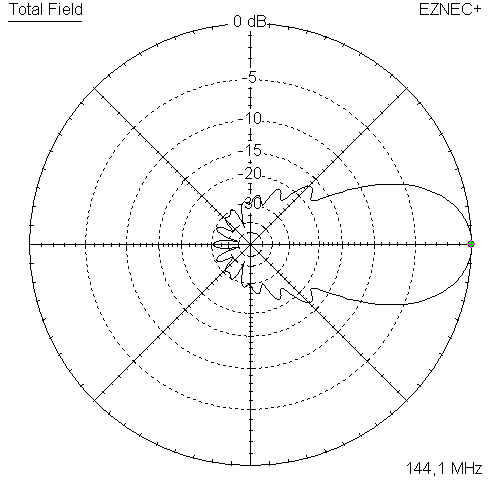
Elevation plots, Antenna Temps. and G/T - ratio at 144.1 MHz
For those, who are less familiar with G/T numbers and Antenna temperatures:
The more positve G/T numbers are, the better they come. Example: -10.83 is better then -10.87 [dB].
The Signal-to-Noise - ratio is not defined by gain alone, but just by gain/antenna temperature = G/T (s. formula at end of page).
Antenne Temp. is captured noise power per band width from all directions in a standardised artificial environment, not the physical temp. of your Yagi.
Depending on the real environment a decrease of that T_ant. by 5 Kelvin can make a noticable difference already on the noise floor of your RX.

|

|

|

|
Original 50 ohms "5-8" Gain vs. isotr. Rad. 13.09 dBi T_ant 249 K* G/T -10.89 dB |
DK7ZB's 28 ohms interpretation Gain vs. isotr. Rad. 13.20 dBi T_ant 255 K* G/T -10.87 dB* |
Fine tuned 28 ohms version Gain vs. isotr. Rad. 13.15 dBi T_ant 250 K* G/T -10.83 dB* |
GTV2-8 wide-band (211 mm or 0.1 wl longer) Gain vs. isotr. Rad. 13.36 dBi T_ant 241 K* G/T -10.46 dB* |
• View Compared Patterns in larger image
RL and SWR plot - DK7ZB 28 ohms interpretation

RL and SWR plot - Fine tuned 28 ohms version // You think that less sidelobes, higher G/T designs must be narrower in band width?

Downloads
EZNEC file of the revised 8 ele. 28 ohms Yagi with Straight Split DE klick
Stacking
Elevation plot and data of 4 Yagi bays
All these 4-Yagi-Bays are created using the DL6WU stacking distance formula

|

|

|

|
Original 50 ohms "5-8" Gain vs. isotr. Rad. 19.0 dBi Gain vs. Dipole 16.9 dBD F/B -34.6 dB F/R -19.7 dB T_ant 238.8 K* G/T -4.79 dB Stacking Dist. h-pol. top-to-bottom 2.59 m side-by-side 2.94 m |
DK7ZB's 28 ohms interpretation Gain vs. isotr. Rad. 19.16 dBi Gain vs. Dipole 17.01 dBD F/B -34.08 dB F/R -25.82 dB T_ant 247.7 K* G/T -4.78 dB* Stacking Dist. h-pol. top-to-bottom 2.66 m side-by-side 3.00 m |
Fine tuned 28 ohms version Gain vs. isotr. Rad. 19.09 dBi Gain vs. Dipole 16.94 dBD F/B -31.60 dB F/R -25.97 dB T_ant 241.6 K* G/T -4.74 dB* Stacking Dist. h-pol. top-to-bottom 2.61 m side-by-side 2.96 m |
GTV2-8 wide-band (211 mm or 0.1 wl longer) Gain vs. isotr. Rad. 19.25 dBi Gain vs. Dipole 17.15 dBD F/B -30.5 dB F/R -28.9 dB T_ant 234.6 K* G/T -4.45 dB* Stacking Dist. h-pol. top-to-bottom 2.63 m side-by-side 2.98 m |
Theoretical numbers, no phasing line losses nor imperfections caused by H-frame included
*) T_sky = 200 K, T_earth = 1000 K as in VE7BQH G/T table
Discussion
At first glance DK7ZB's interpretation looks quite impressive as a single Yagi. Since we all are expecting that using 28 ohms usually
means more band width and a touch of extra gain. However, it does not work out so well with the DK7ZB interpretation in terms of "Low Noise".
It yields more gain then the other two, on the price of more extensive sidelobes. It yields high F/B, which is not all if we design for low noise
as the F/R is rather important too here. Consequently the sum of lobes is so much larger that T_ant rises to a number that the extra gain can
not stand up against when all is added to the G/T number.

Fine tuning using OTHER than just maximise-gain principles produces a 28 ohms version that has more bandwidth and and higher G/T than
the 50 ohms version. Showing 0.16 dB more gain the 4-Yagi-Bay using DK7ZB's interpretation produces the highest Antenna Temperature of all.
The G/T is just 0.01 dB over the 50 ohms version - which might be quieter whenever external noise exceeds the mean number of 1000 K for T_earth
used in the G/T table.
Fine tuning on all parameters produces a much better G/T then pushing gain as a single parameter. OWL / OWA or OWM stand for optimised in
whatever discipline. And usually for a band filter like SWR curve. I would not consider naming any of the above real OW... Yagis.
They are nice designs with enough bandwidth to act "forgiving" on slightly missed out BC numbers. Thats it.
The original Yagi was published in "5-8 ... an expandable 144 MHz Yagi" in Dubus 4/2012, months prior to DK7ZB's OWM and
is listed in the VE7BQH 144 MHz G/T Table since much longer even.
73, Hartmut, DG7YBN
