-
• Main Page
- • Home
• Antennas - • 144 MHz
- Bent dipole GTV
144 MHz YagisGTV 2-7w: 2.7 m wide band width version of the low impedance, yet 50 ohms direct feed Low Noise Yagi with bent DE introduced in Dubus 1/2013
Elevation Plot

- YBN 3+7 SATA Satellite Yagi with 3 ele. for 145 MHz + 7 ele. for 435 MHz for handheld use
Elevation Plots
- YBN 2-2wA 50 ohms direct feed 2 ele. Yagi with high potential as broad beam Contest Stack.
See yourself and compare to DJ9HO Double Quads and 7ZB Oblongs. Full details on 2 and 4 Yagi stacks are given
3D Pattern of 4 x Stack

- YBN 2-5m (5-8)1.6 m high F/R, good willing 50 ohms direct feed Yagi as introduced with bent DE short version of the 5-8 in Dubus 4/2012
Elevation Plot

- YBN 2-6m 1.9 m long, good willing 50 ohms direct feed Yagi, related to the 5-8 project (same positions refl, dipole, D1, D2 ... same size folded dipole)
Elevation Plot
- YBN 2-7m 2.8 m high F/R, good willing 50 ohms direct feed Yagi, related to the 5-8 project (same positions refl, dipole, D1, D2 ... same size folded dipole)
Elevation Plot
- YBN 2-7mz 28 Ω2.8 m high F/R, good willing 28 ohms direct feed Yagi
Elevation Plot

- YBN 2-8m (5-8)3.6 m nice G/T, good willing 50 ohms direct feed Yagi as introduced with bent DE expanded version of the 5-8 in Dubus 4/2012
Actually it seems to be so good that DK7ZB decided to use it as draft for the 8 ele. OWM he just published.
Elevation Plot
- YBN 2-8mz 28 Ω3.6 m 25/28 ohms version of the YBN 2-8m
The stacked 25 ohms Yagi can easily be phased with 50 ohms coax cables
Elevation Plot
- YBN 2-9mz 28 Ω4.3 m high F/R, high G/Ta 28 ohms Yagi
Elevation Plot

- YBN 2-9m4.5 m moderate band width, low Antenna Temperature, good willing 50 ohms direct feed Yagi - a straigh DE version twin to the GTV 2-9m
Elevation Plot
- YBN 2-10w (5-8)5 m wide band, good willing 50 ohms direct feed Yagi as introduced with straight DE expanded version of the 5-8 in Dubus 4/2012
Elevation Plot
- YBN 2-10wz 12.5Ω5.1 m - 144.0 to 144.8 MHz wide band 12 ohms OWL-style Low Noise Yagi with straight DE and very low back lobes only
Elevation Plot
- YBN 2-12wz 12.5Ω6.8 m wide band 12 ohms OWL-style Low Noise Yagi with straight DE and very low back lobes only
Azimuth Plot:
- Bent dipole GTV


YBN 2-5m Yagi with Conventional Driver (Split or Folded Dipole)
This little Yagi has a high F/B, which makes it quite useful as a contest stack,
because the clean rear pattern is kept with stacked arrays.
Contest 4 x stack of YBN 2-5m, built by YO2LSP, used in 2020 IARU ctest by YO5LD/P
7th place in IARU Contest 2020 Single OP class. Congrats!

who succeeded an excellent results for the YO position. - 413 QSO`s , ODX - DA0FF @ 1028 km, Total: 192.955 points.
The antenna works fantastic, in special 2x11 element system. Thank you for your work." ... tnx Edy!
4 x vert. YBN 2-5m built by Zoran, E76C

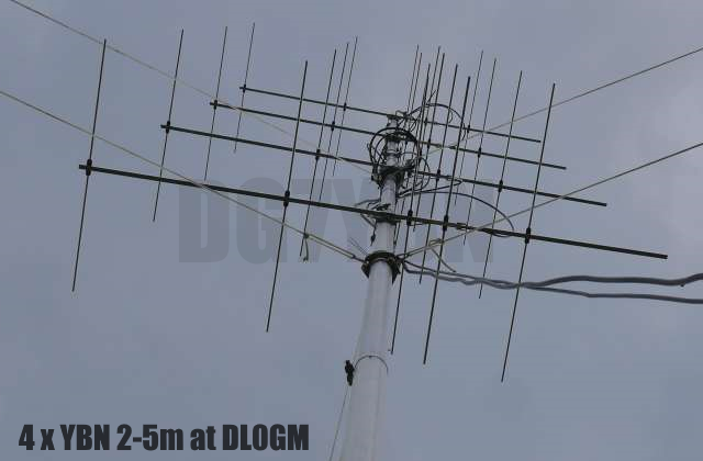
4 x vert. YBN 2-5m at DL0GM built on 15 x 15 mm boom
Update: Stacks with high F/B and CAD drawings as PDF for booms, struts and clamps see end of page

|
The YBN 2-5m is the very pilot model which was used to derive all the "On-Boom-BC-Factors" from (s. Dubus 2/2010). It has been measured about 50 times using various boom dimensions and element lengths. Finally for the 5-8 Yagi concept article (Dubus 4/2012) with folded dipole too. If you stick to the dimensions I give below and use the right i.e. measured symmetrising coax length you virtually can not fail with your build. On right : Stagger stacked 2 x 5 ele. (s. Dubus 1/2014) 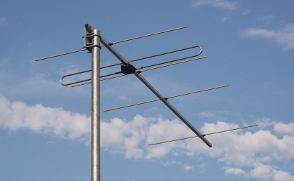
|

|

|
Sketch of boom with option to expand to 8 elem. / The additional 200+ mm on the rear enable mounting it formast as on
photo on left side. Note differing position of D1 when using thin through boom elements or folded dipole as given below.

Performance Data
                     Elem. 4 mm     Elem. 5 mm     Elem. 8 mm
Gain vs. isotr. Rad.  10.2 dBi       10.2 dBi       10.2 dBi
Gain vs. Dipole        8.0 dBD        8.0 dBD        8.0 dBD
-3 dB H-plane         73.0 deg.      72.8 deg.      73.2 deg.
-3 dB E-plane         54.8 deg.      54.6 deg.      54.8 deg.
F/B                  -24.9 dB       -25.2 dB       -24.8 dB
F/R                  -23.4 dB       -23.4 dB       -23.0 dB
Impedance           50/200 ohms         =              =
Mechan. Length        1485 mm           =              =
Electr. Length        0.74 λ            =              =

Stacking Dist. h-pol.
top-to-bottom         1.57 m
side-by-side          2.03 m
Geometry
EZNEC wires for 8 mm elements

Ø6 mm Elements - raw Dimensions exclusive BC
		Refl	 DE	D1	D2	D3
Pos. 		0	 283	403	822	1485
NEC x2          1028.0	 992.0 	956.4	930.5	861.0
Note: element lengths for Ø 8 mm fit 5/16" too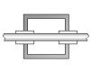
               INSULATED THROUGH BOOM THIN ELEMENTS (BC acc. 6WU)
        Pos.  1/2 Length   BC 20 mm    BC 20 mm   BC 25 mm    BC 1"
                 in NEC     = 2.2      = 2.2     = 3.4       = 3.5

Refl.     0      514.5     1033.2      1031.2     1032.4     10xx.x
DE      283      496.0      994.2       994.2      995.4      9xx.x
D1      403      480.0      966.2       962.2      963.4      9xx.x
D2      822      467.5      942.2       937.2      938.4      9xx.x
D3     1485      433.5      875.2       869.2      870.4      8xx.x

Ele.Ø             5 mm       4 mm        5 mm       5 mm       1/4"

Use WiMo made spare Folded Dipole for their YU7EF line EF0208c
or selfmade one with modified D1 as follows:
Note: for elements 4 mm D1 is of differing length for 5 and 8 ele. Yagi when using a folded DE
ele. 4 mm, Pos. 403 mm, NEC =>  483.0, 20x20 => 968.2, 25x25 => 969.4 mm
ele. 5 mm, Pos. 402 mm, NEC =>  481.0, 20x20 => 964.2, 25x25 => 965.4 mm, 1"x1"=> 96x.x


                        ON BOOM ELEMENTS
        Pos.   1/2 Length   BC 15x15   BC 20x20   BC 25x25    BC 1x1"   BC 20x20   BC 25x25
                 in NEC      = 2.7      = 3.9      = 7.6      = 7.9       = 3.9      = 7.6

Refl.     0      514.5       1031.7     1032.9     1036.6     1034.9     1031.4     1035.1
DE      283      496.0        994.7      995.9      999.6      999.9      995.9      999.6
D1      403      475.0        952.7      953.9      957.6      954.3      947.9      951.6
D2      822      461.0        924.7      925.9      929.6      925.9      918.9      922.6
D3     1485      423.8        850.3      851.5      855.2      851.5      844.9      848.6

Ele.Ø             8 mm         8 mm       8 mm      8 mm        3/8"      10 mm      10 mm
The Driver Dipoles diameter is 10 mm for all examples.
Use EZNEC's Auto-Segmentation at 144.3 MHz.
Use WiMo made Folded Dipole (spare from YU7EF line EF0208c)
or selfmade one with modified D1 as follows:
NEC => 477, Boom 20x20 => 957.9, Boom 25x25 => 961.6 mm, Boom 1"x1"=> 961.9
Folded Dipole
Folded DE tip-to-tip = 990, inner height = 54, diam. = 10 for all builds
Sketch of Folded Dipole
Overview on the stages of the YBN 5- 5 / 8 / 10 ele. project
Here is a very helpful overview on the stages of the YBN 5- 5 / 8 / 10 ele. project provided by Stef, F4EZJ (tnx!).
It shows what elements are shared and different at what positions on the boom for the various combinations
Note: Element lengths given fit elements mounted on a 20 x 20 mm boom with 'standard insulators and M3 screw
Pattern and VSWR Plots
Current distribution


Return Loss and VSWR plot - Version with Folded Dipole from WiMo EF0208c

miniVNA: 144.40 MHz, Z = 49.6 Ohm, SWR = 1.03, RL = -36 dB

Note: this plot is taken on a build without any post tuning on DE or D1.
Just the "On-Boom-BC" added.
121.5 MHz Aircraft Emergency Frq. vers
Aircraft Emergency Frequency version built by F6ANQ and F6BKI.


Geometry for Boom 25 x 25 mm and elements held in hydraulic clamps on request.
Downloads
EZNEC file of this Yagi with Straight Split DE
Read more about building this Yagi in my Article "5-8 ... an extendable 144 MHz Yagi" in Dubus 4/12
Stacking
Stacking Dist.    DL6WU Formula    min. Side Lobes    max. F/B
H-plane               1.57 m           1.41 m          1.90 m
E-plane               2.03 m           1.83 m          2.01 m
Data of 5 over 5 ele. Yagi stack using DL6WU stacking distances -10%

Gain vs. isotr. Rad.  12.7 dBi
Gain vs. Dipole       10.6 dBD
F/B                  -18.5 dB

T_ant                236,0 K*
G/T                 -11,01 dB*
Theoretical numbers, no phasing line losses
nor imperfections caused by H-frame included
Data of 4 bay 5 ele. Yagi stack using DL6WU stacking distances -10%


Stacking Dist.         DL6WU -10%       DL6WU
Gain vs. isotr. Rad.   15.8 dBi        16.1 dBi
Gain vs. Dipole        13.7 dBD        14.0 dBD
F/B                   -21.3 dB        -24.3 dB
F/R                   -26.2 dB        -24.3 dB
T_ant                   231 K*          237 K*
G/T                   -7.85 dB*       -7.64 dB*
Theoretical numbers, no phasing line losses
nor imperfections caused by H-frame included
(*) T_sky = 200 K, T_earth = 1000 K as in VE7BQH G/T table
Elevation plot and data of 4 Yagi vertcal bay using distances for max. F/B
Simulated over perfect ground

                    Free Space Data      Over perfect gnd
Gain vs. isotr. Rad.   16.25 dBi            20.9 dBi
Gain vs. Dipole        14.10 dBD            18.8 dBD
F/B                    -27.5 dB            -26.1 dB
Theoretical numbers, no phasing line lossesnor imperfections caused by H-frame included
Stagger Stacked Contest Array
These Yagis are stacked at 1.90 m and upper & lower Yagi in put 502 mm backwards.
The actual shift for this design stack of 502 mm is a little less than the principle 1/4 λ on 144.3 MHz.
Same as the proposed stacking distance of 1.90 m differs from the 1.57 m per DL6WU formular.
Why is that so?
The principle 1/4 λ is a number based on the theoretical concept of canceling backwards
source by a total of 180° of phase shift. But the individual directive Yagi-Uda antenna holds
phase shifts between parasitic elements and exciter (dipole) in itself. Thus best results for
increased F/B and F/R vary slightly. Same to the difference in vertical stacking distance to DL6WU.
A stacked arrays pattern is an intereference pattern of 2 or more sources i.e. Yagis. A stacking
scheme and goals apart from the standard longs for other optimum stacking distances.
Read abt. the principle here:
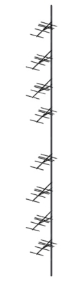
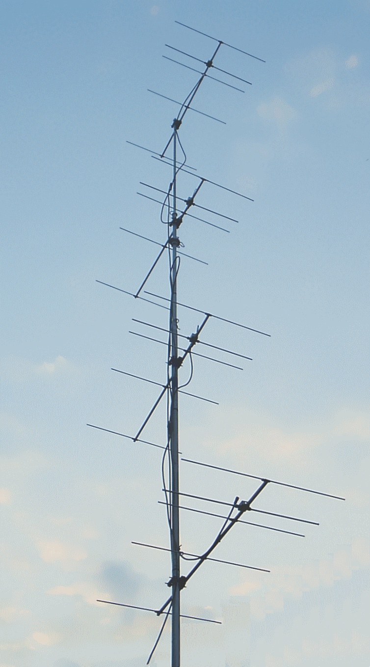
Photo: 4 x YBN 2-5m stacked at 1.90 m vertical and 502 mm inner shift


How to feed?
This idea goes back to Robi, S53WW's
"High Performance Antenna Stack for 2m Contest&Tropo Work", here
Read S53WW's web article or my article published in Dubus 1/2014 & Dubus Technik XIII for
full details of theory about stagger stacking and feeding with 1/4 λ phase lag into
the front Yagis. Note - line lenghts given hold no errors here, but a creative and proven
use of the periodicity of the sinus wave
Image Source Dubus 1/2014: DG7YBN, Stacking beyond DL6WU - Part 2

by the lenghts only, there is NO power splitter needed.
Basics - Impedance
• We take the upper two Yagis: Thats a 50 ohms plus another 50 ohms via 50 ohms coaxes.
Two times 50 ohms in parallel results in 25 ohms at their sum point.
• Then we do same with the lower pair of 50 ohms Yagis.
Two times 50 ohms in parallel results in 25 ohms at their sum point.
• Then we add these Two times 25 ohms in parallel via a transformation coax
consisting of any odd multiples of 1/4 such as 3/4, 5/4 ... wl of 50 ohms coax,
which transforms 25 ohms to 100 ohms in each line.
• Finally when these two lines of odd multiples of 1/4 wl meet, we get 50 ohms
from two times 100 ohms in parallel ... and we are done.
Basics - Phasing
The inner Yagis are displaced by 1/4 λ. To compensate this the feeding coaxes for the
inner Yagis must be are arranged for a phase lag of -90° compared to the outer Yagis. We will
name that phase correcting length 'L-plus'.
But: Feeding with a phase lag of -270° makes +90° as 360° - 270° = + 90° (periodicity of the sinus wave)
Prolonging the lines for the outer Yagis by 270° has same effect as feeding the inner Yagis with -90°.
So that instead of increasing the lengths of coax towards the inner Yagi by 90° of phase angle or 1/4 λ and
have those extra lengths hanging about on the pole with this little trick we can fit the -270° into the
lengths to the outer Yagis.
Phasing Coax Lengths
L_plus: We name that extra 270° length as L_plus in the sketch above. With a v-factor of 0.662 for PE coax it
is 1.031 m. The reason for this is to derive shortest possible feed lines up the pole instead of winding up phasing
lines for the inner Yagis as we see so often on vertical stacks.
L_1: L1 lengths are basically ANY length; but stay clear from any multiple of 1/4 λ x velocity factor.
L_2: L2 lengths are basically ANY odd multiples of 1/4 λ x velocity factor. Here they are 5 x 1/4 λ x V-factor.
At the sum point between 2 Yagis of 50 ohms impedance we find 25 ohms. Any odd multiple of 1/4 λ x velocity factor
brings that back to 50 ohms in the centre feed point. No splitter needed.
Total Lengths
Total lengths must include the lenghts inside likewise the N-T-joiners or whatever self made T-junctions.
Velocity Factor
Lengths L_plus, L1 and L2 given are for PE coax only!
For foam and air coax the effective velocity factor of these at 144 MHz must be applied.
See here
and here
Using 3 N-T-Pieces a flexible, easy to produce phasing line assembly is done at low costs.
Monster Stagger Stack tnx for suggestions to Alexey, RA4SD!
• Full CAD drawings for a 8 x vertical YBN 2-5w stagger stack for download now

• A brief study about a monster stack of 8 x vertical YBN 2-5w at narrow distances

Elevation Pattern (not optimised ... if you really think about a stack like this ask me for optimation of F/B if needed)
• A brief study about a monster stack of 8 x vertical YBN 2-5w at full distances
Elevation Pattern

• A monster stack of 8 x vertical YBN 2-5w at distances optimised for best directivity and F/B
• Geometrical shift between the Yagis is 502 mm
• Vertical stacking distance inside the 2 stacks is 1.90 m
• Vertical stacking distance between the 2 stacks is 3.10 m
With such a rear pattern with a F/B of 38 dB but half power beam width of 56 degr. this stack
gives a good forcast for much less splatter received then most other options.
While this is a free space simulation lets see if the stack maintains this nice attribute when placed
above ground ...
Elevation Pattern above 'perfect ground'

Same on 3D thanks to the capable 3D viewer of 4nec2


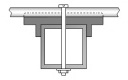
Boom of Yagi in Position 0 mm for formast mounting

Boom of Yagi in Position 502 mm for formast mounting
Strut for Yagi in Position 0 mm for formast mounting
Strut for Yagi in Position 502 mm for formast mounting
Plates for mounitng strut to Yagi (same for both positions)
73, Hartmut, DG7YBN