
• Main Page
- • Home
• Antennas
- • 144 MHz
- Straight Dipole
144 MHz YagisYBN 2-9m: 4.5 m moderate band width, low Antenna Temperature, good willing 50 ohms
direct feed Yagi - a straight DE version twin to the GTV 2-9m
Elevation Plot
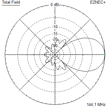
- GTV 2-2m
A 50 ohms direct feed 2 ele. Yagi with bent DE and potential
as broad beam Contest Stack.
It can be used as back-to-back stack:
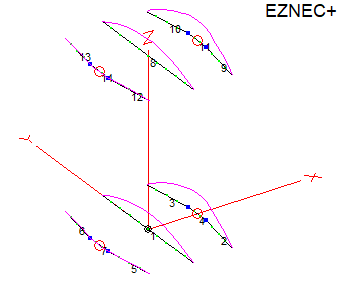
- GTV 2-4w
1.0 m 144-146 MHz wide band width version of the Low Noise Yagi with bent DE as useful
for satellite operation as for contesting thanks to high F/B and small volume of rear quadrants lobs in general.
Elevation Plot at 144.1 MHz

- GTV 2-5m
1.6 m moderate to wide band width version of the Low Noise Yagi with bent DE as useful
for satellite operation as for contesting thanks to high F/B and small volume of rear quadrants lobs in general.
Elevation Plot

- GTV 2-6m
2.4 m moderate band width version of the low impedance, yet 50 ohms
direct feed Low Noise Yagi with bent DE introduced in Dubus 1/2013 Elevation Plot
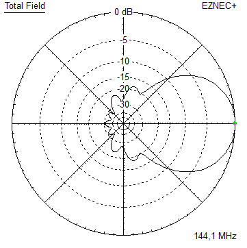
- GTV 2-7w
2.7 m wide band width version of the low impedance, yet 50 ohms
direct feed Low Noise Yagi with bent DE introduced in Dubus 1/2013 Elevation Plot
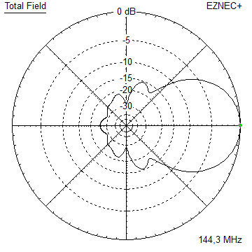
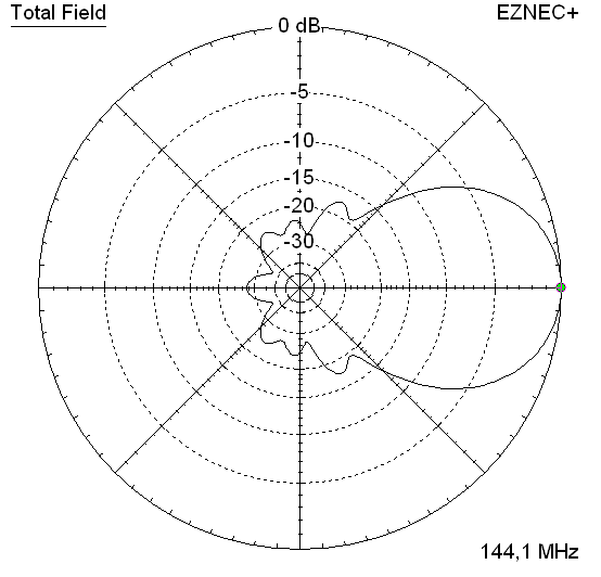
- GTV 2-7n
3.1 m narrow band, max. G/T version of the low impedance, yet 50 ohms
direct feed Low Noise Yagi with bent DE introduced in Dubus 1/2013 Elevation Plot
- GTV 2-8w
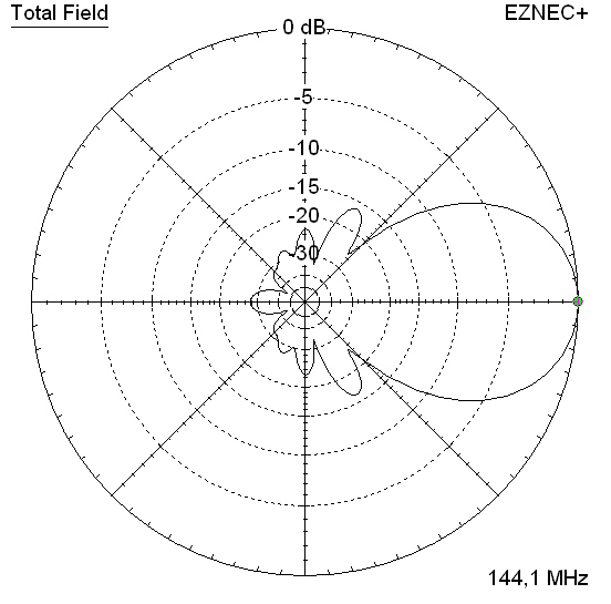
3.7 m wide-band, still good G/T and nice F/B version of the low impedance, yet 50 ohms
direct feed Low Noise Yagi with bent DE introduced in Dubus 1/2013 Elevation Plot
- GTV 2-8n
3.8 m narrow band, max. G/T version of the low impedance, yet 50 ohms
direct feed Low Noise Yagi with bent DE introduced in Dubus 1/2013 Elevation Plot

- GTV 2-9n
4.3 m narrow band, balanced between low Antenna Temp. and G/T version of the low impedance, yet 50 ohms
direct feed Low Noise Yagi with bent DE introduced in Dubus 1/2013 Elevation Plot

- GTV 2-9m
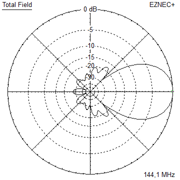
4.5 m moderate band width, low Antenna Temp. version of the low impedance, yet 50 ohms
direct feed Low Noise Yagi with bent DE introduced in Dubus 1/2013 Elevation Plot
- GTV 2-10LT
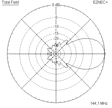
5.1 m moderate band width, lowest Antenna Temp. version of the low impedance, yet 50 ohms
direct feed Low Noise Yagi with bent DE introduced in Dubus 1/2013 Elevation Plot
- GTV 2-11LT
6.0 m moderate band width, lowest Antenna Temp. version of the low impedance, yet 50 ohms
direct feed Low Noise Yagi with bent DE introduced in Dubus 1/2013 Elevation Plot
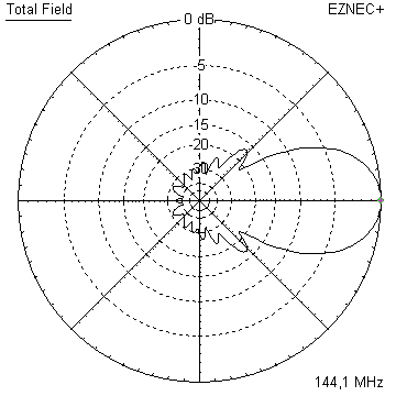
- GTV 2-12m mk2
Improved 6.8 m version of the low impedance, yet 50 ohms
direct feed Low Noise Yagi with bent DE introduced in Dubus 1/2013 Elevation Plot:
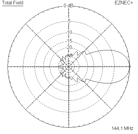
- GTV 2-12n
6.8 m narrow band version of the low impedance, yet 50 ohms
direct feed Low Noise Yagi with bent DE introduced in Dubus 1/2013 Elevation Plot:
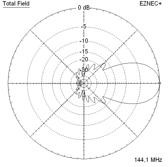
- GTV 2-13m
7.5 m version of the low impedance, yet 50 ohms
direct feed Low Noise Yagi with bent DE introduced in Dubus 1/2013 Elevation Plot:
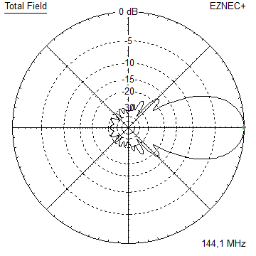
- GTV 2-14w
8.4 m version of the low impedance, yet 50 ohms
direct feed Low Noise Yagi with bent DE introduced in Dubus 1/2013 Elevation Plot
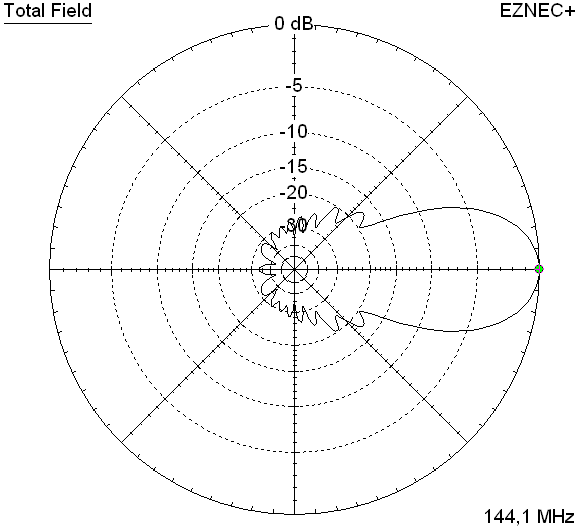
- GTV 2-16w
10 m version of the low impedance, yet 50 ohms
direct feed Low Noise Yagi with bent DE introduced in Dubus 1/2013 Elevation Plot
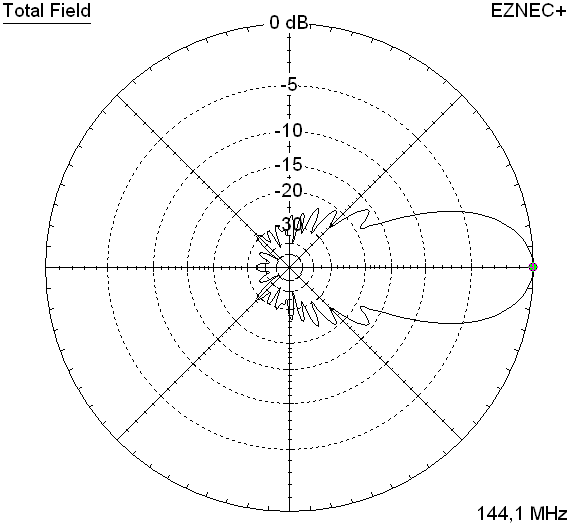
- GTV 2-18w
11.7 m version of the low impedance, yet 50 ohms
direct feed Low Noise Yagi with bent DE introduced in Dubus 1/2013 Elevation Plot
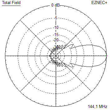
- GTV 2-19m
12.4 m version of the low impedance, yet 50 ohms
direct feed Low Noise Yagi with bent DE introduced in Dubus 1/2013 Elevation Plot

|
....... |
 
 
 Performance Data and Geometry Performance Data and Geometry
 Pattern and VSWR Pattern and VSWR
 Download as File Download as File
 Stacking Stacking
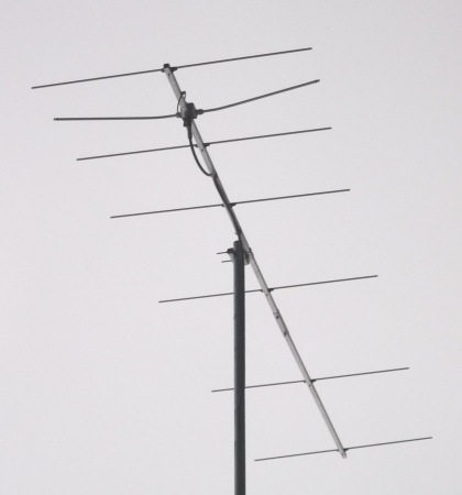
GTV 2-7n Yagi with bent Driven Element
EME + SSB narrow bandwidth version ... strictly G/T breeding
This little Yagi has a high F/B. It may serve as a contest stack or small but effective EME 4-Yagi-Bay.
The bent DE (K6STI style) transforms from approx. 17 ohms to 50 ohms at feed point for direct feed.
The concept of the GTV 7 element goes back to the demand for a narrow band, short Yagi, on which
the characteristics of the bent DE and Boom Corrections could be studied. And that, thanks to being
a responsive narrow bander, with explicite reactions of the real world build. Thus this Yagi lends
itself for getting into building Yagis with bent DE, but also for testing BC factors for unknown
element mounting methods or building styles.
With being a design devoted to narrow bandwidth and low rear lobe volume comes a high performance
in terms of gain and antenna temperature - making a Yagi with very good G/T for a length < 1.5 wl.
GTV 2-7n built by 2M0ETJ

This Yagi is built on 20 x 20 mm boom using 7arrays insulators and 8 mm elements.

Glyn reports: "... tried WITHOUT the tuning stubs (so DE was now -10mm shorter that spec )
swr measured 1.01 @ 144.174 mhz so thats close enough for me ..."
2M0ETJ, 45 W into 1 x GTV 2-7n to IK4FMT in FT8 in nill cdx, QRB = 1608 km

GTV 2-7n built by DG7YBN, Boom 20 x 20 mm, standard insulators, 8 mm elements
Performance Data
Gain vs. isotr. Rad.  12.8 dBi
Gain vs. Dipole       10.7 dBD
-3 dB E-plane         42.4 deg.
-3 dB H-plane         49.8 deg.
F/B                  -27.4 dB
F/R                  -23.2 dB
Impedance               50 ohms
Mechan. Length        2994 mm
Electr. Length        1.44 λ

Stacking Dist. h-pol.
top-to-bottom         2.47 m
side-by-side          2.88 m
Geometry
Nec Geometry with 8 mm Elements

The Segmentation BC is 2.3 mm:
with is derived at by simulating an f_res of 144.20 using auto segmentation at 350 MHz and 144.60 MHz using
auto segmentation at 144.1 MHz and multiplying the resulting delta in freqency by * 5.85 mm/MHz.
        Pos.    1/2 Length  1/2 Length
                  in NEC      in NEC

Refl.     0       505.0       502.0
DE(b)   194      100-471     100-471
DE(a)   275       0-100       0-100
D1      463       480.5       478.0
D2      867       471.0       468.0
D3     1510       460.0       457.5
D4     2302       446.0       443.0
D5     2994       428.0       425.5
                ele. 1/4"   ele. 8 mm

Note: element lengths for Ø 8 mm fit 5/16" too

The Drivers diameter is 10 mm for all examples.
Use EZNEC's Auto-Segmentation at 350 MHz.
"Ready to saw and drill" data for mounting elements on boom with standard insulators on 20 x 20 mm boom including a 30 mm offset from booms end:

Note: The end tips of the pilot antennas bent DE had to be pulled forward by 38 mm
against the NEC model position for best SWR as seen in VNA plot.

How many radio enthusiasts have looked up this website since Febr. 2016?


Pattern and VSWR Plots
Current distribution
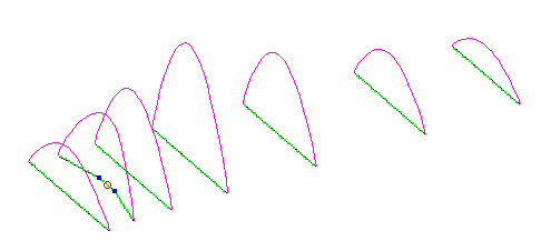
Elevation and Azimuth plot at 144.1 MHz


RL and SWR plot - simulated

RL and SWR plot - measured

Measured RL and SWR
 MHz        RL        SWR
144.2    -39 dB      1.0:1

Downloads
EZNEC file of this Yagi  

Stacking

Stacking Dist.    DL6WU Formula
H-plane               2.47 m
E-plane               2.88 m
Elevation and azimuth plot and data of 4 Yagi bay using DL6WU stacking distances


Gain vs. isotr. Rad.  18.7 dBi
Gain vs. Dipole       16.6 dBD
-3 dB H-plane         19.0 deg.
-3 dB E-plane         22.2 deg.
F/B                  -30.1 dB
F/R                  -24.2 dB
T_ant                242.7 K*
G/T                  -5.15 dB*
Theoretical numbers, no phasing line losses
nor imperfections caused by H-frame included
*) T_sky = 200 K, T_earth = 1000 K as in VE7BQH G/T table

73, Hartmut, DG7YBN

|
|


