-
• Main Page
- • Home
• Antennas - • 144 MHz
- Straight Dipole
144 MHz YagisYBN 2-9m: 4.5 m moderate band width, low Antenna Temperature, good willing 50 ohms direct feed Yagi - a straight DE version twin to the GTV 2-9m
Elevation Plot
- GTV 2-2mA 50 ohms direct feed 2 ele. Yagi with bent DE and potential as broad beam Contest Stack.
It can be used as back-to-back stack:
- GTV 2-4w1.0 m 144-146 MHz wide band width version of the Low Noise Yagi with bent DE as useful for satellite operation as for contesting thanks to high F/B and small volume of rear quadrants lobs in general.
Elevation Plot at 144.1 MHz

- GTV 2-5m1.6 m moderate to wide band width version of the Low Noise Yagi with bent DE as useful for satellite operation as for contesting thanks to high F/B and small volume of rear quadrants lobs in general.
Elevation Plot

- GTV 2-6m2.4 m moderate band width version of the low impedance, yet 50 ohms direct feed Low Noise Yagi with bent DE introduced in Dubus 1/2013
Elevation Plot
- GTV 2-7w2.7 m wide band width version of the low impedance, yet 50 ohms direct feed Low Noise Yagi with bent DE introduced in Dubus 1/2013
Elevation Plot
- GTV 2-7n3.1 m narrow band, max. G/T version of the low impedance, yet 50 ohms direct feed Low Noise Yagi with bent DE introduced in Dubus 1/2013
Elevation Plot
- GTV 2-8w3.7 m wide-band, still good G/T and nice F/B version of the low impedance, yet 50 ohms direct feed Low Noise Yagi with bent DE introduced in Dubus 1/2013
Elevation Plot
- GTV 2-8n3.8 m narrow band, max. G/T version of the low impedance, yet 50 ohms direct feed Low Noise Yagi with bent DE introduced in Dubus 1/2013
Elevation Plot

- GTV 2-9n4.3 m narrow band, balanced between low Antenna Temp. and G/T version of the low impedance, yet 50 ohms direct feed Low Noise Yagi with bent DE introduced in Dubus 1/2013
Elevation Plot

- GTV 2-9m4.5 m moderate band width, low Antenna Temp. version of the low impedance, yet 50 ohms direct feed Low Noise Yagi with bent DE introduced in Dubus 1/2013
Elevation Plot
- GTV 2-10LT5.1 m moderate band width, lowest Antenna Temp. version of the low impedance, yet 50 ohms direct feed Low Noise Yagi with bent DE introduced in Dubus 1/2013
Elevation Plot
- GTV 2-11LT6.0 m moderate band width, lowest Antenna Temp. version of the low impedance, yet 50 ohms direct feed Low Noise Yagi with bent DE introduced in Dubus 1/2013
Elevation Plot
- GTV 2-12m mk2Improved 6.8 m version of the low impedance, yet 50 ohms direct feed Low Noise Yagi with bent DE introduced in Dubus 1/2013
Elevation Plot:
- GTV 2-12n6.8 m narrow band version of the low impedance, yet 50 ohms direct feed Low Noise Yagi with bent DE introduced in Dubus 1/2013
Elevation Plot:
- GTV 2-13m7.5 m version of the low impedance, yet 50 ohms direct feed Low Noise Yagi with bent DE introduced in Dubus 1/2013
Elevation Plot:
- GTV 2-14w8.4 m version of the low impedance, yet 50 ohms direct feed Low Noise Yagi with bent DE introduced in Dubus 1/2013
Elevation Plot
- GTV 2-16w10 m version of the low impedance, yet 50 ohms direct feed Low Noise Yagi with bent DE introduced in Dubus 1/2013
Elevation Plot
- GTV 2-18w11.7 m version of the low impedance, yet 50 ohms direct feed Low Noise Yagi with bent DE introduced in Dubus 1/2013
Elevation Plot
- GTV 2-19m12.4 m version of the low impedance, yet 50 ohms direct feed Low Noise Yagi with bent DE introduced in Dubus 1/2013
Elevation Plot

- Straight Dipole


GTV 2-8w Yagi with bent Driven Element
Wide-band version ... a "unconditionally stable" yet high G/T Yagi that shows least
degradation with wet elements or snow on and thus easy to reproduce parameters.
Yagis generally show a degradation in performance with wet elements. Which is due to
water film or drops hanging on the elements. Thus they appear thicker when wet. Which detunes
the Yagi both in gain and pattern as in SWR. The GTV 2-8w shows very little degradation for
its G/T. If you are looking for a Yagi suitable for worst weather condx ... this one might be it.
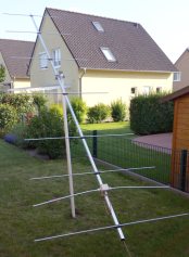
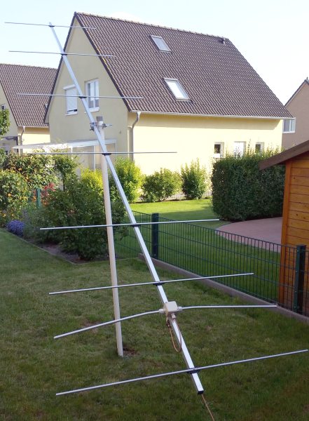
2 x vert. GTV 2-8w and GTV 70-19m by S50K


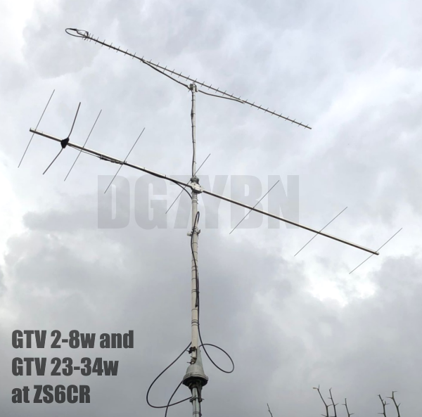
GTV 2-8w and GTV 23-34w at ZS6CR
3 x vertical GTV 2-8w by OM3KSI,
Amateur Radio Club of Faculty of Aeronautics, Technical University in Kosice

• 7th place in IARU VHF ctest Low Power Multi-Operator class with this stack.

• Details: Dipole shape (flat aluminium bar 12 x 4 mm), hydraulic clamps (Stauff), no extra BC
Photo Credit: Peter, OM8WG. Tnx Peter!
GTV 2-8w xpol built by Peter, DJ4TC
Coaxes fed from rear, with the 1/4 wl lines out rearwards

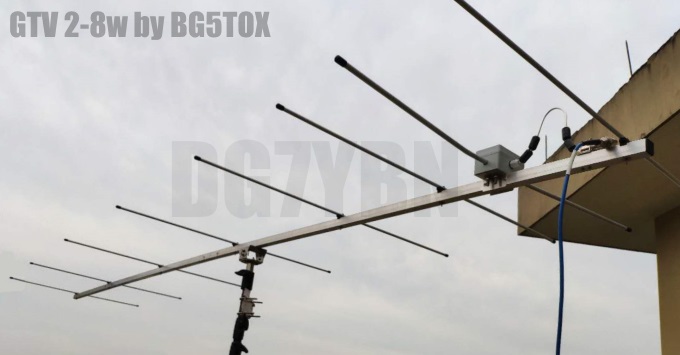
GTV 2-8w built by Xu Da, BG5TOX
GTV 2-8w xpol built by Toralf, DJ8MS
Toralf reports the Yagi being quieter than his former Flexa Yagi and significantly quieter than a 9 ele. XPOL by M2.
GTV 2-8w xpol built by Thomas, M0ABA
Coaxes fed from rear, with the 1/4 wl lines out rearwards

GTV 2-8w xpol built by Peter, DJ4TC
coaxes fed from rear, rebuilt to route the 1/4 wl lines out rearwards which results in clearer VSWR

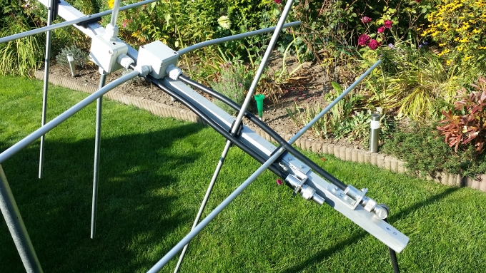
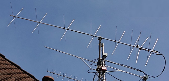
GTV 2-8w by Peter, DL1RPL
→ Place mouse over images to enlarge
 |
 |
|
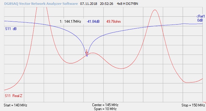
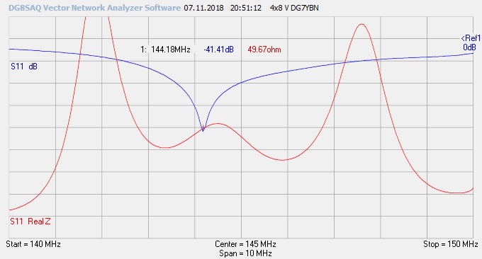
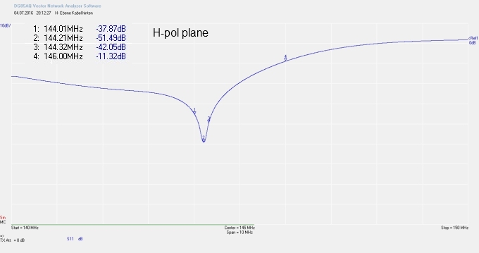
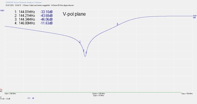
| GTV 2-8w by Peter, DL1RPL | and VNA plot on low pole; Geometry per table 2 |
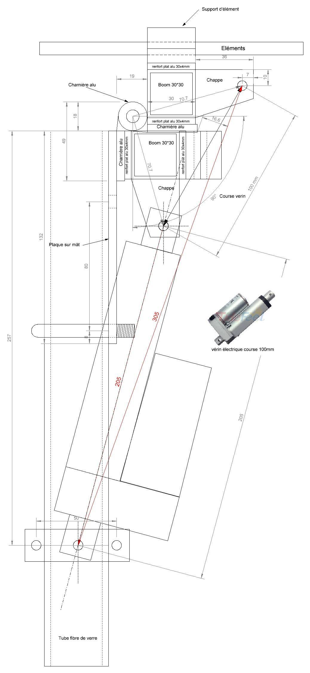
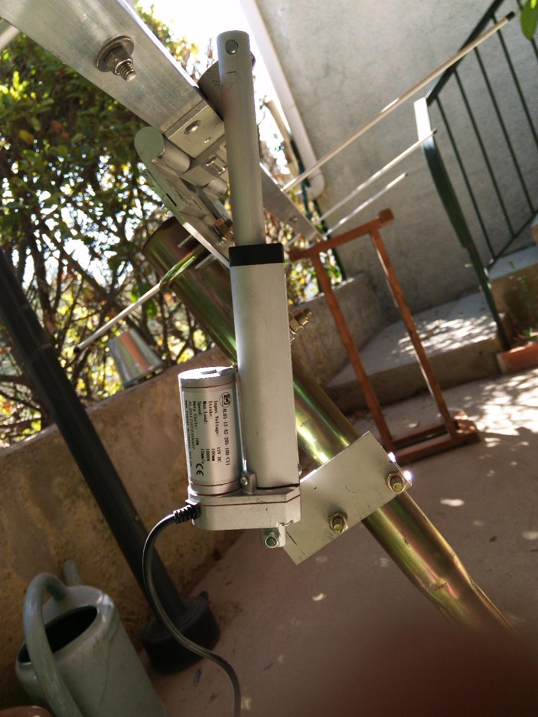
Philippe, F4GRT built a GTV 2-8w self modified to 145 MHz with polarisation rotator

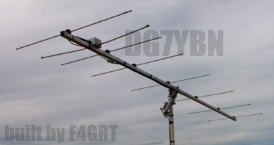


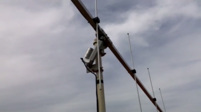
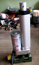
Drive and pivot: click to enlarge
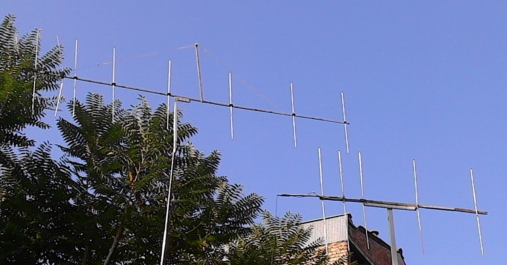
GTV 2-8w modified for FM Radio built by Hossein Khamooshi
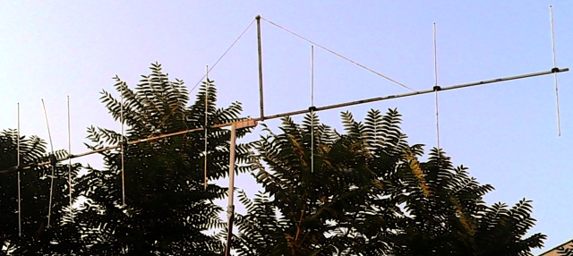
Boom and element holders are made from a wooden lace. Below: comparing against a 5 element design
This medium length Yagi is anchored around 144.3 MHz to produce guaranted G/T at a moderate
T_ant from 144.0 to 145.0 MHz. The bent DE (K6STI style) transforms from low impedance to 50 ohms
at feed point for direct feed.
An easy to reproduce Cross Yagi:
2 x or 4 x GTV2-8wx will do for even EME expeditions which may benefit from the Yagis stability if
mounted on a short mast with the reflectors only a few feet above ground.
Wet weather degradation analysis by courtesy of UR5EAZ:

1). G/T DRY (40.8 deg x 46.6 deg; 2.98m x 2.63m; DielC=1; Thk=0mm).
Results of Tant: 233.9K; 3.6K; 234.6K; -4.45dB

2). G/T WET Degradation: (2.98m x 2.63m; DielC=8; Thk=0,1mm).
Results of Tant: 233.3K; 4.0K; 234.3K; -4.4dB (!)

- Very good stab.[ility] of the antenna!
- Very good pattern!
- Good VSWR.

Владимир UR5EAZ.
Performance Data
                     Elem. 8 mm
Gain vs. isotr. Rad.  13.4 dBi
Gain vs. Dipole       11.2 dBD
-3 dB H-plane         40.8 deg.
-3 dB E-plane         46.6 deg.
F/B                  -27.8 dB
F/R                  -22.8 dB
Impedance               50 ohms
VSWR Band Width     1.12:1 *
Mechan. Length        3696 mm
Electr. Length        1.78 λ

Stacking Dist. h-pol.
top-to-bottom         2.63 m
side-by-side          2.98 m

*) as in VE7BQH G/T table = at 145.00 MHz
Geometry
4 mm elements - without BC, SBC addedThe Drivers diameter is 10 mm for all examples. Use EZNEC's Auto-Segmentation at 380 MHz.Refl. DE D1 D2 D3 D4 D5 D6 Pos. 0 275 431 819 1466 2198 2984 3696 Lgth. 1030.2 992.2 973.6 953.8 930.2 914.6 898.0 868.2 4 mm elements insulated through boom BC: Use SM5BSZ BC numbers and nylon rivets on square boom as shown on BC-page 3/16 in or 4.763 mm elements, 1/2 in DE - without BC, SBC added Refl. DE D1 D2 D3 D4 D5 D6 Pos. 0 275 431 819 1466 2198 2984 3696 Lgth. 1028.2 988.2 970.6 950.2 925.7 909.6 892.7 862.2 8 mm Elemente - without BC, but with SBC of 3.2 mm
Refl. DE D1 D2 D3 D4 D5 D6 Pos. 0 275 431 819 1466 2198 2984 3696 Länge 1023.2 989.2 958.2 937.2 910.2 893.2 875.2 845.2 8 mm elements - on 20 x 20 mm boom with suitable BC and SBC Refl. DE D1 D2 D3 D4 D5 D6 Pos. 0 275 431 819 1466 2198 2984 3696 Lgth. 1027.1 993.1 962.1 941.1 914.1 897.1 879.1 849.1 Applies to all diameters SegmentationBC = +3.2 mm = (144.9 MHz - 144.35 MHz) * 5.85 mm/MHz BaseBC (20x20) = +3.9 mm for semi-insulated on boom Total = +7.1 mm Note: element lengths for Ø 8 mm fit 5/16" too
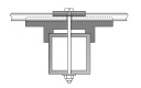
Sketch of Driver Cell
Note: The tips of the bent dipole in many cases have to be brought more straigth, towards D1, by up to approx. 20 ... 30 mm.
Connect the Yagi to a VNA or SWR meter and adjust bending angle for best Return Loss.
• Bent DE Online Calculator as web app
This Yagi with 4 mm elements through a 20 x 20 x 2 mm boom
|
|
Ele. 4.0 mm DE 10.0 mm Boom 20 x 20 x 2 mm |
"Ready to saw and drill" data for mounting elements through boom with BC according SM5BSZ's BC.exe:
Note: with through Boom BC it is important to stick to the boom end offsets given below!
This table is only valid for:
Boom shape: square
Boom dim: 1 x 1 in
Wall thickn.: 0.063 in = 1.6 mm
Holes in boom: 7.8 mm
Offset rear: 40 mm
Offset front: 40 mm
Includes an SBC of 3.22 mm

This Yagi in Imperial Measures with 3/16 in elements through a 1 x 1 in boom
|
|
Ele. 3/16 in DE 1/2 in Boom 1 x 1 x 0.063 in |
"Ready to saw and drill" data for mounting elements through boom with BC according SM5BSZ's BC.exe:
Note: with through Boom BC it is important to stick to the boom end offsets given below!
This table is only valid for:
Boom shape: square
Boom dim: 1 x 1 in
Wall thickn.: 0.063 in = 1.6 mm
Holes in boom: 7.8 mm
Offset rear: 40 mm
Offset front: 40 mm
Includes an SBC of 3.22 mm
![]()
This Yagi with 8 mm elements on a 20 x 20 mm boom with standard insulators

|
Ele. 8.0 mm DE 10 mm Boom 20 x 20 mm |
"Ready to saw and drill" data for mounting elements on boom with BC according DG7YBN for standard insulators as sold by Konni, Nuxcom, WiMo, 7arrays:
Includes an SBC of 3.22 mm
This Yagi with 8 mm elements on a 25 x 25 mm boom with high insulators by 7arrays.com
|
Ele. 8.0 mm DE 10 mm Boom 25 x 25 mm |
"Ready to saw and drill" data for mounting elements on boom with BC according DG7YBN for type "insulator high 25 x 25 mm" by 7arrays:
Includes an SBC of 3.22 mm

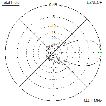
Pattern and VSWR Plots
Elevation and Azimuth plot at 144.1 MHz

RL and SWR plot - simulated / 144 - 145 Mhz
RL and SWR plot - simulated / 140 - 150 Mhz
Gain, F/B and F/R plot - simulated
Downloads
EZNEC file of this Yagi with 4 mm elements
EZNEC file of this Yagi with 8 mm elements
EZNEC file of this Yagi as xpol with 8 mm elements on boom 25 x 25 mm
EZNEC file of the 4 Yagi Bay
An array of 8 x GTV 2-8wx for tropo and EME

Cross Yagi / X-Pol = GTV 2-8wx
on boom 25 x 25 mm: offset of element plane from centre is:
25 mm x 0.5 = 12.5 mm
plastic insulator clearance is 1.7 mm
half element diameter = position of wire in NEC = 8 mm x 0.5 = 4 mm
=> total offset = 12.5 + 1.7 + 4 = 18.2 mm => simulation carried out with 20 mm
on boom offset: second (vertical plane) = -80 mm
Performance Data
Gain vs. isotr. Rad.  13.36 dBi
Gain vs. Dipole       11.2 dBD
-3 dB H-plane         43.6 deg.
-3 dB E-plane         43.6 deg.
F/B                  -27.8 dB
F/R                  -25.5 dB
Impedance               50 ohms
VSWR Band Width     1.11:1 *
Mechan. Length        3776 mm

Stacking Dist.
top-to-bottom         2.80 m
side-by-side          2.80 m

*) as in VE7BQH G/T table = at 145.00 MHz
| Pattern plot | SWR plane 1 | and SWR plane 2 |
|

|
|
Imperial Measures XPOL Yagi with rear boom offset for rear feed
|
|
Ele. 3/16 in DE 1/2 in Boom 1 x 1 x 0.125 in |
"Ready to saw and drill" data for mounting elements through boom with BC according SM5BSZ's BC.exe:
Note: with through Boom BC it is important to stick to the boom end offsets given below!
This table is only valid for:
Boom shape: square
Boom dim: 1 x 1 in
Wall thickn.: 0.125 in = 3.2 mm
Holes in boom: 7.8 mm
Offset rear: 430 resp. 510 mm
Offset front: 40 mm
Includes an SBC of 3.22 mm
![]()
This Yagi with 8 mm elements on a 25 x 25 mm boom with standard insulators
|
|
Ele. 8.0 mm DE 10 mm Boom 25 x 25 mm |
"Ready to saw and drill" data for XPOL Yagi - mounting 8 mm elements on 25 x 25 mm boom with insulators as sold by Konni, Nuxcom, WiMo, 7arrays using DG7YBN BC:
Includes an SBC of 3.22 mm
This Yagi with 8 mm elements on a 20 x 20 mm boom with standard insulators
|
|
Ele. 8.0 mm DE 10 mm Boom 20 x 20 mm |
"Ready to saw and drill" data for XPOL Yagi - mounting 8 mm elements on 20 x 20 mm boom with insulators as sold by Konni, Nuxcom, WiMo, 7arrays using DG7YBN BC:
With a boom 20 x 20 mm one should think about using guy ropes to add strength to the boom against shag and wind force.
Includes an SBC of 3.22 mm

 This array is 7.50 x 2.50 m in summed up stacking distances. Gain = 21.8 dBi ex. phasing lines
This Yagi with a bent Folded Dipole
The straight split bent dipole can be replaced with a bent folded dipole like in any non-bent Yagi design.
In doing so the transformation ratio of 1:4 remains. The bent folded dipole versions impedance is 200 ohms.
The folded dipole itself is of Ø 6 mm; I recommend an 'elements through boom' built.
So that the folded dipole is centered in the element plane for best symmetry in the elevation pattern.
4nec2 Geometry Editor showing the Folded Dipole in Element Plane

Geometry of the Folded Dipole
In the model we use the center of the tube, regardless of its actual diameter.
With this height is 64 mm, span width is 980 mm. Adding the real diameter of 10 mm we end up with
inner height = 54 mm, outer span width = 990 mm, see sketch

Note: Folded Dipole mounting in plastic brackets compensation
Whatever plastic block is used to suspend or mount the dipoles wires will need to be compensated
by adding ~ 0.1 mm per millimeter of wire running in plastic. If you attach a 20 mm plastic block on top
of the boom to lead the dipoles upper wire a length of 2.0 mm / 2 = 1.0 mm needs to be added to the dipoles
span width. Assumed it runs free of contact to plastic on the down side.
We use factor 1/2 in a folded dipole then since it is a full wave loop.

|
Attenzione!
If symmetrical to element plane this folded dipole replaces a straight dipole with out any change to D1. However if not in element plane by means of an offset of elements by mounting on boom on insulators D1 must be adapted. |
VSWR and Return Loss with a Folded Dipole in Element Plane

Stacking
Stacking Dist.    DL6WU Formula
H-plane               2.630 m
E-plane               2.984 m
Elevation and azimuth plot and data of 4 Yagi bay using DL6WU stacking distances
Gain vs. isotr. Rad.  19.3 dBi
Gain vs. Dipole       17.1 dBD
-3 dB H-plane         18.2 deg.
-3 dB E-plane         21.0 deg.
F/B                  -30.5 dB
F/R                  -28.9 dB
T_los                  3.4 K
T_ant                234.6 K*
G/T                  -4.45 dB*
Theoretical numbers, no phasing line losses
nor imperfections caused by H-frame included
*) T_sky = 200 K, T_earth = 1000 K as in VE7BQH G/T table
73, Hartmut, DG7YBN