-
• Main Page
- • Home
• Antennas - • 144 MHz
- Straight Dipole
144 MHz YagisYBN 2-9m: 4.5 m moderate band width, low Antenna Temperature, good willing 50 ohms direct feed Yagi - a straight DE version twin to the GTV 2-9m
Elevation Plot
- GTV 2-2mA 50 ohms direct feed 2 ele. Yagi with bent DE and potential as broad beam Contest Stack.
It can be used as back-to-back stack:
- GTV 2-4w1.0 m 144-146 MHz wide band width version of the Low Noise Yagi with bent DE as useful for satellite operation as for contesting thanks to high F/B and small volume of rear quadrants lobs in general.
Elevation Plot at 144.1 MHz

- GTV 2-5m1.6 m moderate to wide band width version of the Low Noise Yagi with bent DE as useful for satellite operation as for contesting thanks to high F/B and small volume of rear quadrants lobs in general.
Elevation Plot

- GTV 2-6m2.4 m moderate band width version of the low impedance, yet 50 ohms direct feed Low Noise Yagi with bent DE introduced in Dubus 1/2013
Elevation Plot
- GTV 2-7w2.7 m wide band width version of the low impedance, yet 50 ohms direct feed Low Noise Yagi with bent DE introduced in Dubus 1/2013
Elevation Plot
- GTV 2-7n3.1 m narrow band, max. G/T version of the low impedance, yet 50 ohms direct feed Low Noise Yagi with bent DE introduced in Dubus 1/2013
Elevation Plot
- GTV 2-8w3.7 m wide-band, still good G/T and nice F/B version of the low impedance, yet 50 ohms direct feed Low Noise Yagi with bent DE introduced in Dubus 1/2013
Elevation Plot
- GTV 2-8n3.8 m narrow band, max. G/T version of the low impedance, yet 50 ohms direct feed Low Noise Yagi with bent DE introduced in Dubus 1/2013
Elevation Plot

- GTV 2-9n4.3 m narrow band, balanced between low Antenna Temp. and G/T version of the low impedance, yet 50 ohms direct feed Low Noise Yagi with bent DE introduced in Dubus 1/2013
Elevation Plot

- GTV 2-9m4.5 m moderate band width, low Antenna Temp. version of the low impedance, yet 50 ohms direct feed Low Noise Yagi with bent DE introduced in Dubus 1/2013
Elevation Plot
- GTV 2-10LT5.1 m moderate band width, lowest Antenna Temp. version of the low impedance, yet 50 ohms direct feed Low Noise Yagi with bent DE introduced in Dubus 1/2013
Elevation Plot
- GTV 2-11LT6.0 m moderate band width, lowest Antenna Temp. version of the low impedance, yet 50 ohms direct feed Low Noise Yagi with bent DE introduced in Dubus 1/2013
Elevation Plot
- GTV 2-12m mk2Improved 6.8 m version of the low impedance, yet 50 ohms direct feed Low Noise Yagi with bent DE introduced in Dubus 1/2013
Elevation Plot:
- GTV 2-12n6.8 m narrow band version of the low impedance, yet 50 ohms direct feed Low Noise Yagi with bent DE introduced in Dubus 1/2013
Elevation Plot:
- GTV 2-13m7.5 m version of the low impedance, yet 50 ohms direct feed Low Noise Yagi with bent DE introduced in Dubus 1/2013
Elevation Plot:
- GTV 2-14w8.4 m version of the low impedance, yet 50 ohms direct feed Low Noise Yagi with bent DE introduced in Dubus 1/2013
Elevation Plot
- GTV 2-16w10 m version of the low impedance, yet 50 ohms direct feed Low Noise Yagi with bent DE introduced in Dubus 1/2013
Elevation Plot
- GTV 2-18w11.7 m version of the low impedance, yet 50 ohms direct feed Low Noise Yagi with bent DE introduced in Dubus 1/2013
Elevation Plot
- GTV 2-19m12.4 m version of the low impedance, yet 50 ohms direct feed Low Noise Yagi with bent DE introduced in Dubus 1/2013
Elevation Plot

- Straight Dipole
GTV 2-7w Yagi with bent Driven Element
For the given bandwidth this Yagi shows quite a low Antenna Temperature and a moderate gain for its length. The bent DE (K6STI style) transforms to 50 ohms at feed point for direct feed. Design date of issue: 2020.09.18
GTV 2-7w xpol built by_ZS6JON


GTV 2-7w 3D pattern plot at 144,3 MHz
Performance Data
Specs: with 8 mm elements @ 144.1 MHz
Gain vs. isotr. Rad.  12.3 dBi
Gain vs. Dipole       10.1 dBD
-3 dB E-plane         44.6 deg.
-3 dB H-plane         52.8 deg.
F/B                  -25.0 dB
F/R                  -22.1 dB
Impedance               50 ohms
VSWR Band Width       1.01:1 *
Mechan. Length        2691 mm
Electr. Length        1.29 λ

Stacking Dist. h-pol. (144.1 MHz)
top-to-bottom         2.34 m or 7.7 ft
side-by-side          2.74 m or 9.0 ft

Stacking Dist. h-pol. (145.5 MHz)
top-to-bottom         2.32 m or 7.6 ft
side-by-side          2.71 m or 8.9 ft

*) as in VE7BQH G/T table = at 145.00 MHz
How many VHF operators have been looking up this design since Sept 2020?
Geometry
This Yagi with 8 mm elements on a 20 x 20 mm boom with standard insulators

|
Ele. 8.0 mm DE 10 mm Boom 20 x 20 mm |
|

"Ready to saw and drill" data for mounting elements on boom with BC according DG7YBN for standard insulators as sold by WiMo, Tino's Funkshop, HF-Kits NL, 7arrays:
Includes an SBC of 1.17 mm

SegmentationBC = +1.17 mm = (144.3 MHz - 144.5 MHz) * 5.85 mm/MHz
BaseBC (20x20) = +3.90 mm for semi-insulated on boom
Total          = +5.07 mm
Note: element lengths for Ø 8 mm fit 5/16" too
The Drivers diameter is 10 mm for all examples.
The EZNEC model is done with Auto-Segmentation at 400 MHz

Ø 3/16 inch Elements, 3/8 inch Dipole - Through Boom - Dimensions (BC acc. SM5BSZ's BC.exe)
Imperial Boom 1"
|
This table is only valid for: Boom shape: square Boom dim: 1 x 1 inch Wall thickn.: 1.6 mm Holes in boom: 7.7 mm Offset rear: 40 mm Offset front: 40 mm |
Note: All the above include a "Segmentation Density Correction" (SBC) of 1.17 mm per element.
Note: with through Boom BC it is important to stick to the boom end offsets given below!
Read abt. the SBC here
![]()
Sketch of Bent Dipole

Pattern and VSWR Plots
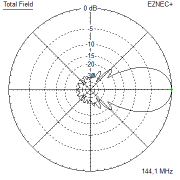
Elevation and Azimuth plot at 144.1 MHz


Elevation and Azimuth plot at 144.5 MHz


Elevation and Azimuth plot at 145.0 MHz

Elevation and Azimuth plot at 146.0 MHz
Finally: A comparison between elevation patterns DK7ZB "7-El.-Ultra-Wideband-Yagi 50 Ohm, 6 MHz SWR < 1,15" and shorter GTV 2-7w.

RL and SWR plots - simulated

Gain and F/B, F/R

Return Loss (dB) plotted on the full xpol, both planed combined by ZS6JON, span 120 - 171 MHz:

Downloads
None so far.
Stacking
Stacking Dist.    DL6WU Formula (144.1 MHz)
E-plane               2.74 m or 9.0 ft
H-plane               2.34 m or 7.7 ft
Plot and data of 2 vertically stacked GTV 2-7w using DL6WU stacking distances
Antenna View & Elevation Pattern

Plot and data of 3 vertically stacked GTV 2-7w using DL6WU stacking distances
Antenna View & Elevation Pattern
Plot and data of 4 vertically stacked GTV 2-7w using DL6WU stacking distances
Antenna View & Elevation Pattern

Plot and data of 4 in H-config stacked GTV 2-7w using DL6WU stacking distances
Elevation & Azimuth Pattern


Excel version of AGTC_lite screenshot (Tsky = 290 K, Tearth = 5400 K)
Mind that this Yagi covers the whole 2 m band with a Return Loss better -35 dB or VSWR 1:03 in theory.
So the Antenna G/T will not be as low as you might be used to from comparaing a GTV Yagi to others in
the VE7BQH Antenna Tables.
73, Hartmut, DG7YBN