-
• Main Page
- • Home
• Antennas - • 144 MHz
- Straight Dipole
144 MHz YagisYBN 2-9m: 4.5 m moderate band width, low Antenna Temperature, good willing 50 ohms direct feed Yagi - a straight DE version twin to the GTV 2-9m
Elevation Plot
- GTV 2-2mA 50 ohms direct feed 2 ele. Yagi with bent DE and potential as broad beam Contest Stack.
It can be used as back-to-back stack:
- GTV 2-4w1.0 m 144-146 MHz wide band width version of the Low Noise Yagi with bent DE as useful for satellite operation as for contesting thanks to high F/B and small volume of rear quadrants lobs in general.
Elevation Plot at 144.1 MHz

- GTV 2-5m1.6 m moderate to wide band width version of the Low Noise Yagi with bent DE as useful for satellite operation as for contesting thanks to high F/B and small volume of rear quadrants lobs in general.
Elevation Plot

- GTV 2-6m2.4 m moderate band width version of the low impedance, yet 50 ohms direct feed Low Noise Yagi with bent DE introduced in Dubus 1/2013
Elevation Plot
- GTV 2-7w2.7 m wide band width version of the low impedance, yet 50 ohms direct feed Low Noise Yagi with bent DE introduced in Dubus 1/2013
Elevation Plot
- GTV 2-7n3.1 m narrow band, max. G/T version of the low impedance, yet 50 ohms direct feed Low Noise Yagi with bent DE introduced in Dubus 1/2013
Elevation Plot
- GTV 2-8w3.7 m wide-band, still good G/T and nice F/B version of the low impedance, yet 50 ohms direct feed Low Noise Yagi with bent DE introduced in Dubus 1/2013
Elevation Plot
- GTV 2-8n3.8 m narrow band, max. G/T version of the low impedance, yet 50 ohms direct feed Low Noise Yagi with bent DE introduced in Dubus 1/2013
Elevation Plot

- GTV 2-9n4.3 m narrow band, balanced between low Antenna Temp. and G/T version of the low impedance, yet 50 ohms direct feed Low Noise Yagi with bent DE introduced in Dubus 1/2013
Elevation Plot

- GTV 2-9m4.5 m moderate band width, low Antenna Temp. version of the low impedance, yet 50 ohms direct feed Low Noise Yagi with bent DE introduced in Dubus 1/2013
Elevation Plot
- GTV 2-10LT5.1 m moderate band width, lowest Antenna Temp. version of the low impedance, yet 50 ohms direct feed Low Noise Yagi with bent DE introduced in Dubus 1/2013
Elevation Plot
- GTV 2-11LT6.0 m moderate band width, lowest Antenna Temp. version of the low impedance, yet 50 ohms direct feed Low Noise Yagi with bent DE introduced in Dubus 1/2013
Elevation Plot
- GTV 2-12m mk2Improved 6.8 m version of the low impedance, yet 50 ohms direct feed Low Noise Yagi with bent DE introduced in Dubus 1/2013
Elevation Plot:
- GTV 2-12n6.8 m narrow band version of the low impedance, yet 50 ohms direct feed Low Noise Yagi with bent DE introduced in Dubus 1/2013
Elevation Plot:
- GTV 2-13m7.5 m version of the low impedance, yet 50 ohms direct feed Low Noise Yagi with bent DE introduced in Dubus 1/2013
Elevation Plot:
- GTV 2-14w8.4 m version of the low impedance, yet 50 ohms direct feed Low Noise Yagi with bent DE introduced in Dubus 1/2013
Elevation Plot
- GTV 2-16w10 m version of the low impedance, yet 50 ohms direct feed Low Noise Yagi with bent DE introduced in Dubus 1/2013
Elevation Plot
- GTV 2-18w11.7 m version of the low impedance, yet 50 ohms direct feed Low Noise Yagi with bent DE introduced in Dubus 1/2013
Elevation Plot
- GTV 2-19m12.4 m version of the low impedance, yet 50 ohms direct feed Low Noise Yagi with bent DE introduced in Dubus 1/2013
Elevation Plot

- Straight Dipole
GTV 2-8n Yagi with bent Driven Element
EME + SSB narrow bandwidth version ... strictly G/T breeding
This medium length Yagi is gain oriented for maximum G/T at moderate T_ant for a Low Noise Yagi.
The bent DE (K6STI style) transforms from low impedance to 50 ohms at feed point for direct feed.
Date of issue of this design is 2013-04-28

Performance Data
Gain vs. isotr. Rad.  13.6 dBi
Gain vs. Dipole       11.5 dBD
-3 dB H-plane         39.0 deg.
-3 dB E-plane         44.2 deg.
F/B                  -28.9 dB
F/R                  -25.1 dB
Impedance               50 ohms
VSWR Band Width     1.68:1 *
Mechan. Length        3820 mm
Electr. Length        1.84 λ

Stacking Dist. h-pol.
top-to-bottom         2.77 m
side-by-side          3.12 m

*) as in VE7BQH G/T table = at 145.00 MHz
Geometry

SegmentationBC = +2.3 mm = (144.6 MHz - 144.2 MHz) * 5.85 mm/MHz
BaseBC (20x20) = +3.9 mm for semi-insulated on boom
Total = +6.2 mm
Note: element lengths for Ø 8 mm fit 5/16" too
The Drivers diameter is 10 mm for all examples.
Table 1: GTV 2-8n, 8 mm elements on a 20 x 20 mm boom:
"Ready to saw and drill" data for mounting elements on boom with BC according DG7YBN for standard insulators as sold by WiMo, Tino's Funkshop, HF Kits.nl, 7arrays:
|
Boom shape: square Boom: 20 x 20 mm Offset rear: 40 mm Offset front: 40 mm |
|

Note: This includes a "Segmentation Density Correction" (SBC) of 2.34 mm

Table 2: GTV 2-8n, 8 mm elements on a 25 x 25 mm boom:
"Ready to saw and drill" data for mounting elements on boom with BC according DG7YBN for standard insulators as sold by WiMo, Tino's Funkshop, HF Kits.nl, 7arrays:
|
Boom shape: square Boom: 25 x 25 mm Offset rear: 40 mm Offset front: 40 mm |
|

Note: This includes a "Segmentation Density Correction" (SBC) of 2.34 mm

Sketch of Bent Dipole

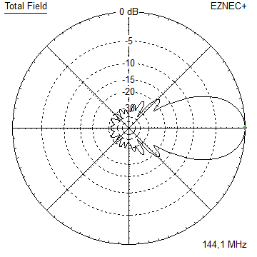
Pattern and VSWR Plots
Elevation and Azimuth plot at 144.1 MHz


RL and SWR plot - simulated

Downloads
EZNEC file of this Yagi
Stacking

Stacking Dist.    DL6WU Formula
H-plane               2.765 m
E-plane               3.116 m
Elevation and azimuth plot and data of 4 Yagi bay using DL6WU stacking distances


Gain vs. isotr. Rad.  19.5 dBi
Gain vs. Dipole       17.4 dBD
-3 dB H-plane         17.4 deg.
-3 dB E-plane         19.8 deg.
F/B                  -31.1 dB
F/R                  -26.5 dB
T_los                  5.0 K
T_ant                240.9 K*
G/T                  -4.29 dB*
Theoretical numbers, no phasing line losses
nor imperfections caused by H-frame included
*) T_sky = 200 K, T_earth = 1000 K as in VE7BQH G/T table
73, Hartmut, DG7YBN