-
• Main Page
- • Home
• Antennas - • 144 MHz
- Straight Dipole
144 MHz YagisYBN 2-9m: 4.5 m moderate band width, low Antenna Temperature, good willing 50 ohms direct feed Yagi - a straight DE version twin to the GTV 2-9m
Elevation Plot
- GTV 2-2mA 50 ohms direct feed 2 ele. Yagi with bent DE and potential as broad beam Contest Stack.
It can be used as back-to-back stack:
- GTV 2-4w1.0 m 144-146 MHz wide band width version of the Low Noise Yagi with bent DE as useful for satellite operation as for contesting thanks to high F/B and small volume of rear quadrants lobs in general.
Elevation Plot at 144.1 MHz

- GTV 2-5m1.6 m moderate to wide band width version of the Low Noise Yagi with bent DE as useful for satellite operation as for contesting thanks to high F/B and small volume of rear quadrants lobs in general.
Elevation Plot

- GTV 2-6m2.4 m moderate band width version of the low impedance, yet 50 ohms direct feed Low Noise Yagi with bent DE introduced in Dubus 1/2013
Elevation Plot
- GTV 2-7w2.7 m wide band width version of the low impedance, yet 50 ohms direct feed Low Noise Yagi with bent DE introduced in Dubus 1/2013
Elevation Plot
- GTV 2-7n3.1 m narrow band, max. G/T version of the low impedance, yet 50 ohms direct feed Low Noise Yagi with bent DE introduced in Dubus 1/2013
Elevation Plot
- GTV 2-8w3.7 m wide-band, still good G/T and nice F/B version of the low impedance, yet 50 ohms direct feed Low Noise Yagi with bent DE introduced in Dubus 1/2013
Elevation Plot
- GTV 2-8n3.8 m narrow band, max. G/T version of the low impedance, yet 50 ohms direct feed Low Noise Yagi with bent DE introduced in Dubus 1/2013
Elevation Plot

- GTV 2-9n4.3 m narrow band, balanced between low Antenna Temp. and G/T version of the low impedance, yet 50 ohms direct feed Low Noise Yagi with bent DE introduced in Dubus 1/2013
Elevation Plot

- GTV 2-9m4.5 m moderate band width, low Antenna Temp. version of the low impedance, yet 50 ohms direct feed Low Noise Yagi with bent DE introduced in Dubus 1/2013
Elevation Plot
- GTV 2-10LT5.1 m moderate band width, lowest Antenna Temp. version of the low impedance, yet 50 ohms direct feed Low Noise Yagi with bent DE introduced in Dubus 1/2013
Elevation Plot
- GTV 2-11LT6.0 m moderate band width, lowest Antenna Temp. version of the low impedance, yet 50 ohms direct feed Low Noise Yagi with bent DE introduced in Dubus 1/2013
Elevation Plot
- GTV 2-12m mk2Improved 6.8 m version of the low impedance, yet 50 ohms direct feed Low Noise Yagi with bent DE introduced in Dubus 1/2013
Elevation Plot:
- GTV 2-12n6.8 m narrow band version of the low impedance, yet 50 ohms direct feed Low Noise Yagi with bent DE introduced in Dubus 1/2013
Elevation Plot:
- GTV 2-13m7.5 m version of the low impedance, yet 50 ohms direct feed Low Noise Yagi with bent DE introduced in Dubus 1/2013
Elevation Plot:
- GTV 2-14w8.4 m version of the low impedance, yet 50 ohms direct feed Low Noise Yagi with bent DE introduced in Dubus 1/2013
Elevation Plot
- GTV 2-16w10 m version of the low impedance, yet 50 ohms direct feed Low Noise Yagi with bent DE introduced in Dubus 1/2013
Elevation Plot
- GTV 2-18w11.7 m version of the low impedance, yet 50 ohms direct feed Low Noise Yagi with bent DE introduced in Dubus 1/2013
Elevation Plot
- GTV 2-19m12.4 m version of the low impedance, yet 50 ohms direct feed Low Noise Yagi with bent DE introduced in Dubus 1/2013
Elevation Plot

- Straight Dipole


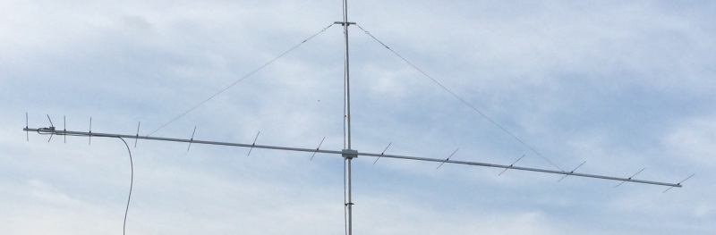
GTV 2-14w Yagi with bent Driven Element
From EME + SSB band to 145.5 MHz - Wideband Antenna Version (OWA-style)
This Yagi has an exceptionally low side- and back lobe volume for its length. It may serve as single antenna for Tropo, Meteor Scatter or even EME or make a very quiet contest antenna due to its high F/B and clean overall pattern. The bent DE (K6STI style) transforms from approx. 17 ohms to 50 ohms at feed point. The GTV 2-14 challenges the popular DK7ZB 12 ele. 28 ohms Yagi. Being just 0.15 λ or 312 mm longer it provides significantly better G/T at more bandwidth, s. data taken from VE7BQH G/T table (G/T is better the more positive the number is):
               Length.       Z         Gain      Gain of 4 Bay   Antenna Temp.   G/T of 4 Bay   VSWR Bandwidth
GTV 2-14w      8278 mm    50 ohms    14.1 dBD      20.0 dBD         218 K         -1.25 dB         1.07:1
DK7ZB 12 ele.  7960 mm    28 ohms    14.2 dBD      20.1 dBD         237 K         -1.49 dB         1.46:1
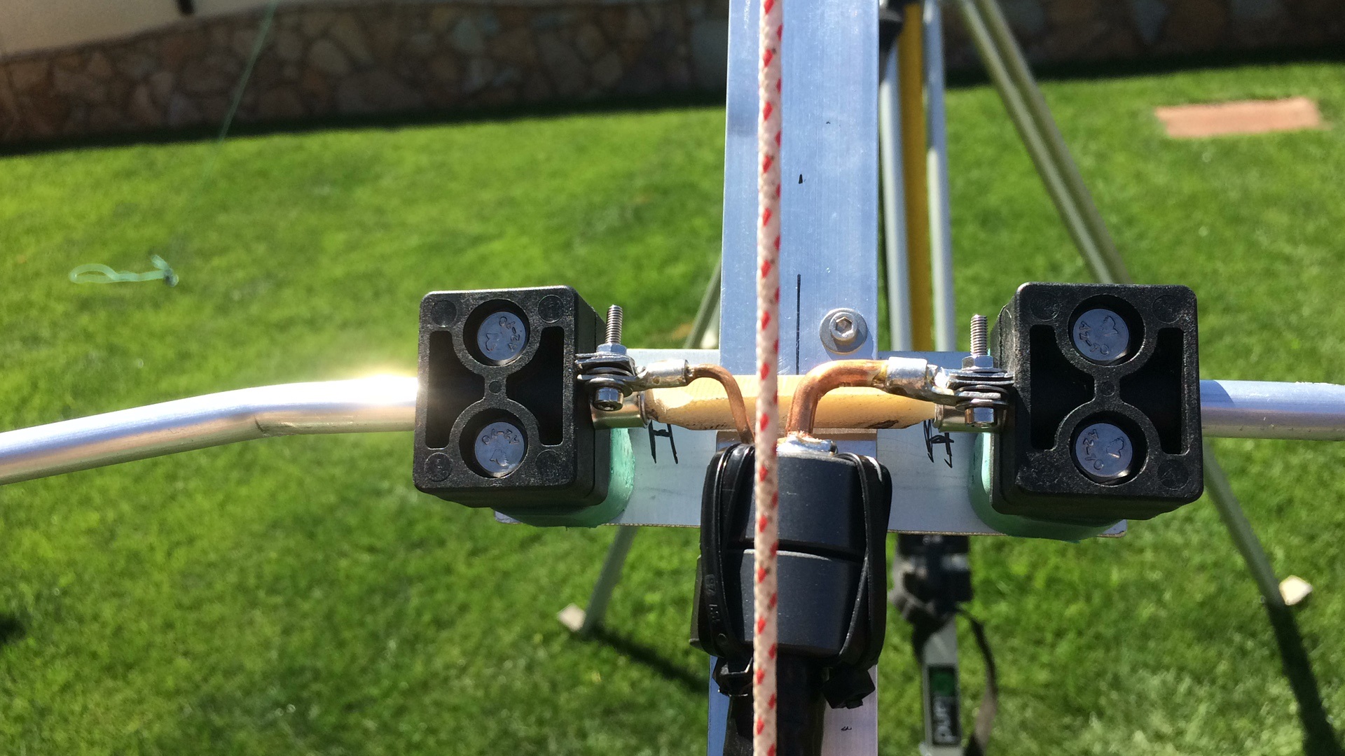
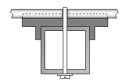
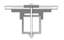
2 x vert. GTV 2-14w at DK0NA, built by Michael, DB6NT

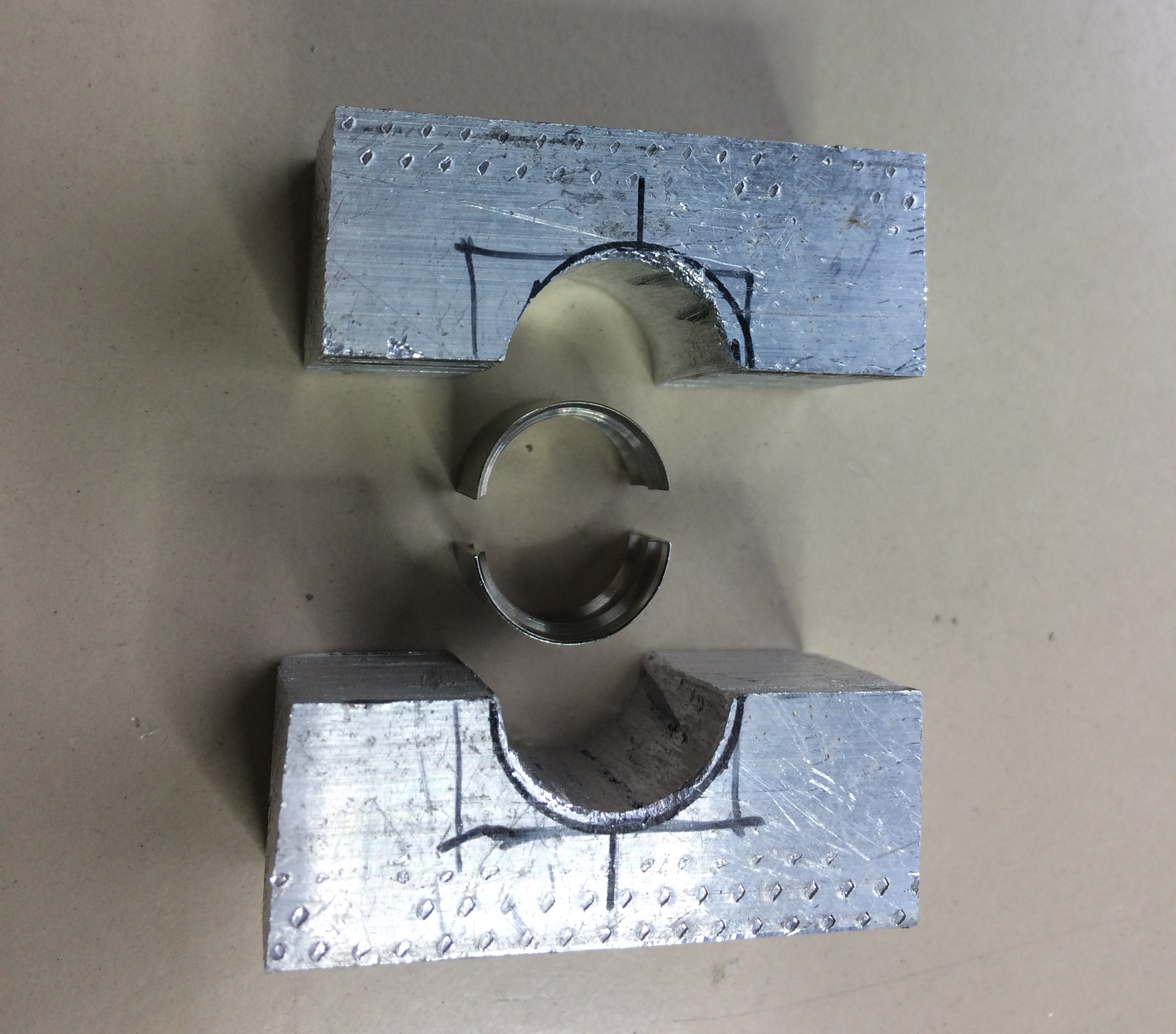
Mast clamp for 25 x 25 mm boom, built by DB6NT.


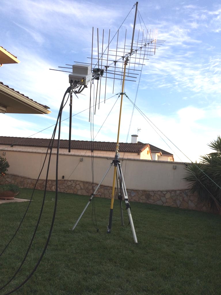
GTV 2-14w xpol built by Juan, EA4CYQ

|
Juan reports:
|

I hope it plays well in your specific browser.
GTV 2-14w built by Helmut, DK8SG
Boom is 25 x 25 mm, Elements 8 mm on 'insulators high on 25 x 25 mm' by 7arrays
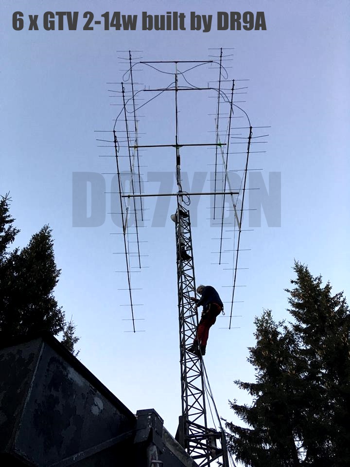
6 x GTV 2-14w built by DR9A
Boom is 25 x 25 mm, Elements 8 mm on 'insulators high on 25 x 25 mm' by 7arrays
Click on image to enlarge:


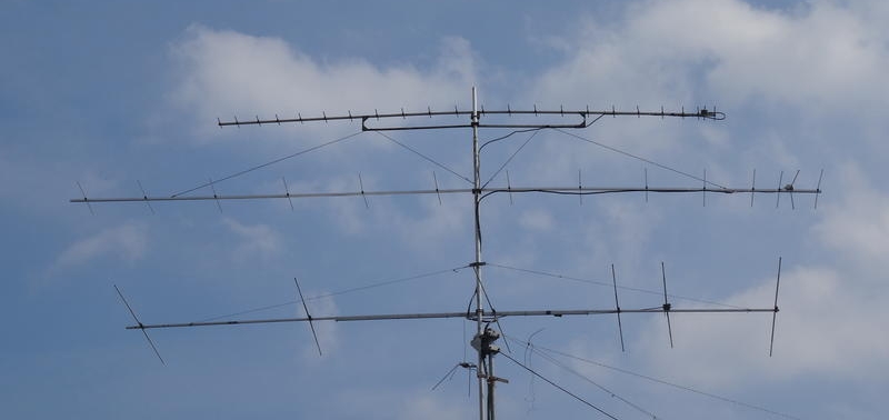
A GTV 2-14w X-pol shortened to 10 elements by Wolf, DF7KB
... and a 26 ele. DL6WU as "counterpoise". Note the Blade Dipole version for both planes made of thick stripes of aluminum. The GTV 2-14 minus 4 ele. keeps a relatively clean pattern, just loses a bit of band width and 1.7 dB of forward gain.

2 x vertical stack of GTV 2-14w by DL2VL
These Yagis are built with Ø 8 mm ele. + standard insulators, DG7YBN on-boom-BC, mid boom section is 25 x 25 mm, front & rear section 20 x 20 mm.
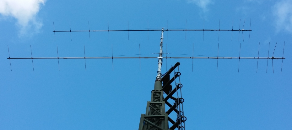

that verify its simulated properties down the page
Marconi Memorial Contest, International Results 2017: DL2VL #13. QSO'S 319, points 114,252
< Official Results MMC 2015 for DL; DL2VL: "All in all I managed an All-Time-Location-Record."

2016-04-12: GTV 2-14w on 25 x 25 mm Boom at Christian, DL8YE
GTV 2-14w built by Radioclub Köszeg - HA1KYY
Good neighbourhood - DG7YBN 2 m GTV Long Yagi above a bay of DJ9BV 70 cm Long Yagis

Read Jozsef, HA1VQ's comments using the GTV 2-14w in contests
The Yagi is built on a 35 mm round boom, 8 mm elements + 13 mm clearence to boom with a BC of 8 mm incl. the SBC.
Performance Data
                      ele. 1/4"     ele. 8 mm
Gain vs. isotr. Rad.  16.2 dBi      16.2 dBi
Gain vs. Dipole       14.1 dBD      14.1 dBD
-3 dB E-plane         29.8 deg.     29.8 deg.
-3 dB H-plane         31.6 deg.     31.6 deg.
F/B                  -33.0 dB      -33.3 dB
F/R                  -28.1 dB      -28.3 dB
Impedance               50 ohms       =
Mechan. Length        8278 mm         =
Electr. Length        3.98 λ

Stacking Dist. h-pol.    DL6WU
top-to-bottom           3.82 m
side-by-side            4.05 m

Stacking Dist. h-pol.   max. G/T
top-to-bottom           4.00 m
side-by-side            4.20 m
|

|
Geometry

 Pos. Full Length Full Length Full Length incl. BC 1/2 Length Full Length incl. BC
Free Space Free Space Free Space on 25x25 Boom in NEC Free Space on 25x25 Boom
incl. SBC incl. SBC incl. SBC
Refl. 0 1023.7 1023.3 1019.1 1026.7 508.5 1017.0 1026.3
DE(b) 232 983.7** 982.7 982.7 989.3 100-490.5 981.0 989.3
DE(a) 286 100.0 100.0 100.0 100.0 0-100 100.0 100.0
D1 421 972.2 971.3 967.2 974.3 479.5 959.0 968.3
D2 707 964.7 963.8 957.9 965.5 475.5´ 951.0 960.3
D3 1246 943.1 942.0 936.1 943.7 463.75 927.5 936.8
D4 1886 928.0 926.8 919.5 927.1 455.5 911.0 920.3
D5 2628 916.3 915.0 907.9 915.5 449.2 898.4 907.7
D6 3419 905.1 903.8 895.3 902.9 443.0 886.0 895.3
D7 4239 893.7 892.2 884.1 891.7 437.0 874.0 883.3
D8 5086 885.1 883.8 875.3 882.9 432.5 865.0 874.3
D9 5939 879.3 877.8 869.5 877.1 429.5 859.0 868.3
D10 6771 878.9 877.3 868.5 876.1 429.0 858.0 867.3
D11 7580 871.9 870.3 862.3 869.9 425.5 851.0 860.3
D12 8278 859.9 858.4 850.1 857.7 419.0 838.0 847.3
ele. 5 mm ele. 1/4" ele. 1/4" ele. 8 mm* ele. 8 mm* ele. 8 mm* ele. 8 mm*
        Pos.    Full Length    Full Length    Full Length      incl. BC    1/2 Length     Full Length      incl. BC
                 Free Space     Free Space     Free Space   on 25x25 Boom    in NEC        Free Space    on 25x25 Boom
                 incl. SBC     incl. SBC      incl. SBC
Refl.     0      1023.7         1023.3          1019.1        1026.7          508.5          1017.0         1026.3
DE(b)   232       983.7**        982.7          982.7           989.3       100-490.5        981.0          989.3
DE(a)   286       100.0          100.0          100.0           100.0         0-100           100.0          100.0
D1      421       972.2          971.3          967.2           974.3         479.5           959.0          968.3
D2      707       964.7          963.8          957.9           965.5         475.5´          951.0          960.3
D3     1246       943.1          942.0          936.1           943.7         463.75          927.5          936.8
D4     1886       928.0          926.8          919.5           927.1         455.5           911.0          920.3
D5     2628       916.3          915.0          907.9           915.5         449.2           898.4          907.7
D6     3419       905.1          903.8          895.3           902.9         443.0           886.0          895.3
D7     4239       893.7          892.2          884.1           891.7         437.0           874.0          883.3
D8     5086       885.1          883.8          875.3           882.9         432.5           865.0          874.3
D9     5939       879.3          877.8          869.5           877.1         429.5           859.0          868.3
D10    6771       878.9          877.3          868.5           876.1         429.0           858.0          867.3
D11    7580       871.9          870.3          862.3           869.9         425.5           851.0          860.3
D12    8278       859.9          858.4          850.1           857.7         419.0           838.0          847.3
                ele. 5 mm      ele. 1/4"       ele. 1/4"     ele. 8 mm*     ele. 8 mm*      ele. 8 mm*     ele. 8 mm*
• Insulated through Boom builds: => Use Full Length incl. SegmentationBC in Free Space Use DL6WU/G3SEK BC number for insulated through boom (add +3.4 mm to free length for 25x25 mm boom) or apply SM5BSZ's BC.exe (see my BC page
• On Boom builds: => Use "incl BC on 25x25 mm boom" numbers and standard insulators plus M3 screw
SegmentationBC = +1.7 mm = (144.4 MHz - 144.1 MHz) * 5.85 mm/MHz
BaseBC (25x25) = +7.6 mm for semi-insulated on boom
Total          = +9.3 mm
(*) Note: element lengths for Ø 8 mm fit 5/16" too (**) Dipole diam. 0.375 in
The Drivers diameter is 10 mm for all examples. Use EZNEC's Auto-Segmentation at 350 MHz.
This Yagi with 8 mm elements on a 25 x 25 mm boom with standard insulators
|
|
Ele. 8.0 mm DE 10 mm Boom 25 x 25 mm |
"Ready to saw and drill" data for mounting elements on boom with BC according DG7YBN for standard insulators as sold by Konni, Nuxcom, WiMo, 7arrays:
Includes an SBC of 1.70 mm

This Yagi with 8 mm elements on a 25 x 25 mm boom with high insulators by 7arrays.com
|
Ele. 8.0 mm DE 10 mm Boom 25 x 25 mm |
"Ready to saw and drill" data for mounting elements on boom with BC according DG7YBN for type "insulator high 25 x 25 mm" by 7arrays:
Includes an SBC of 1.70 mm

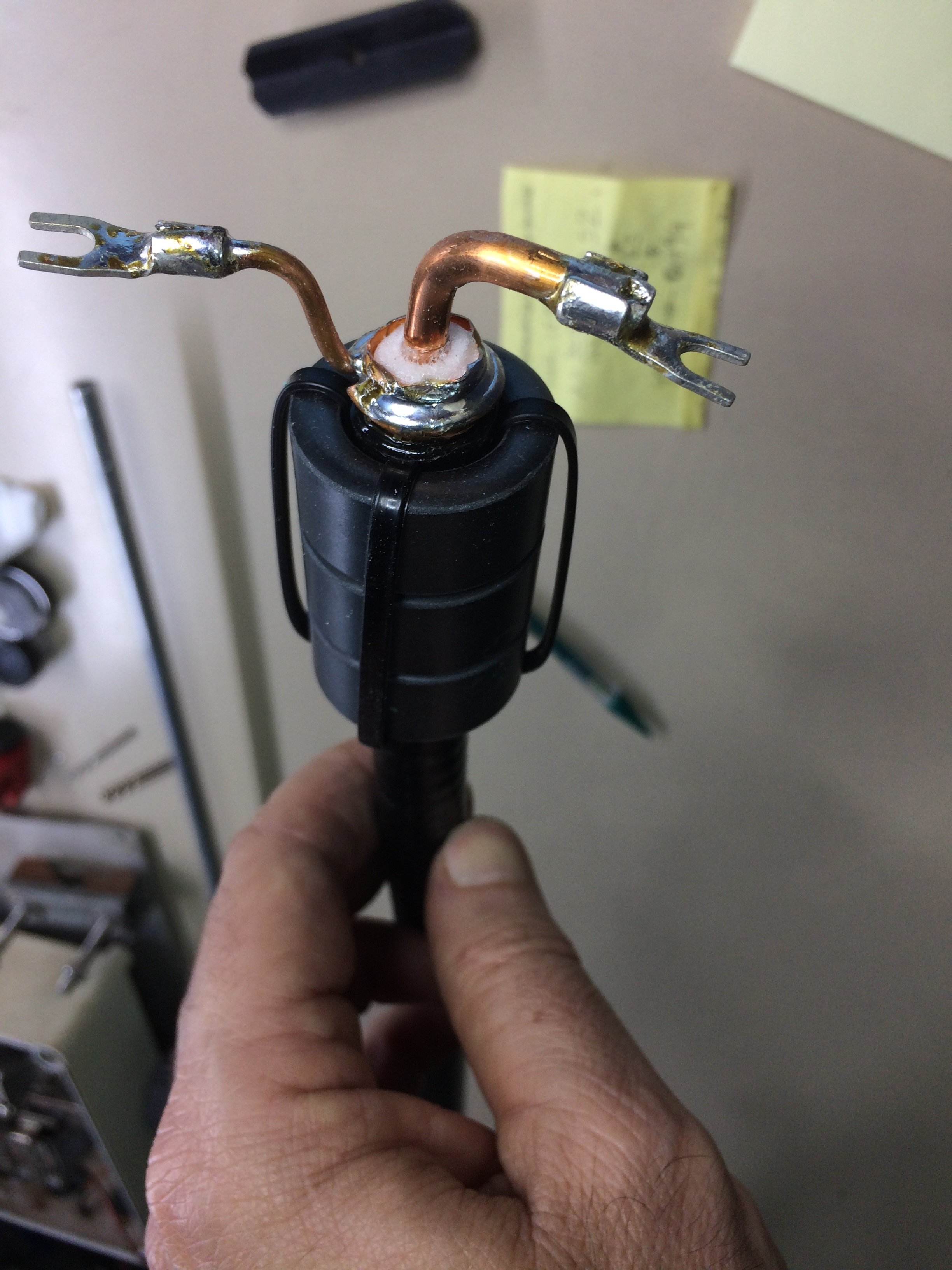
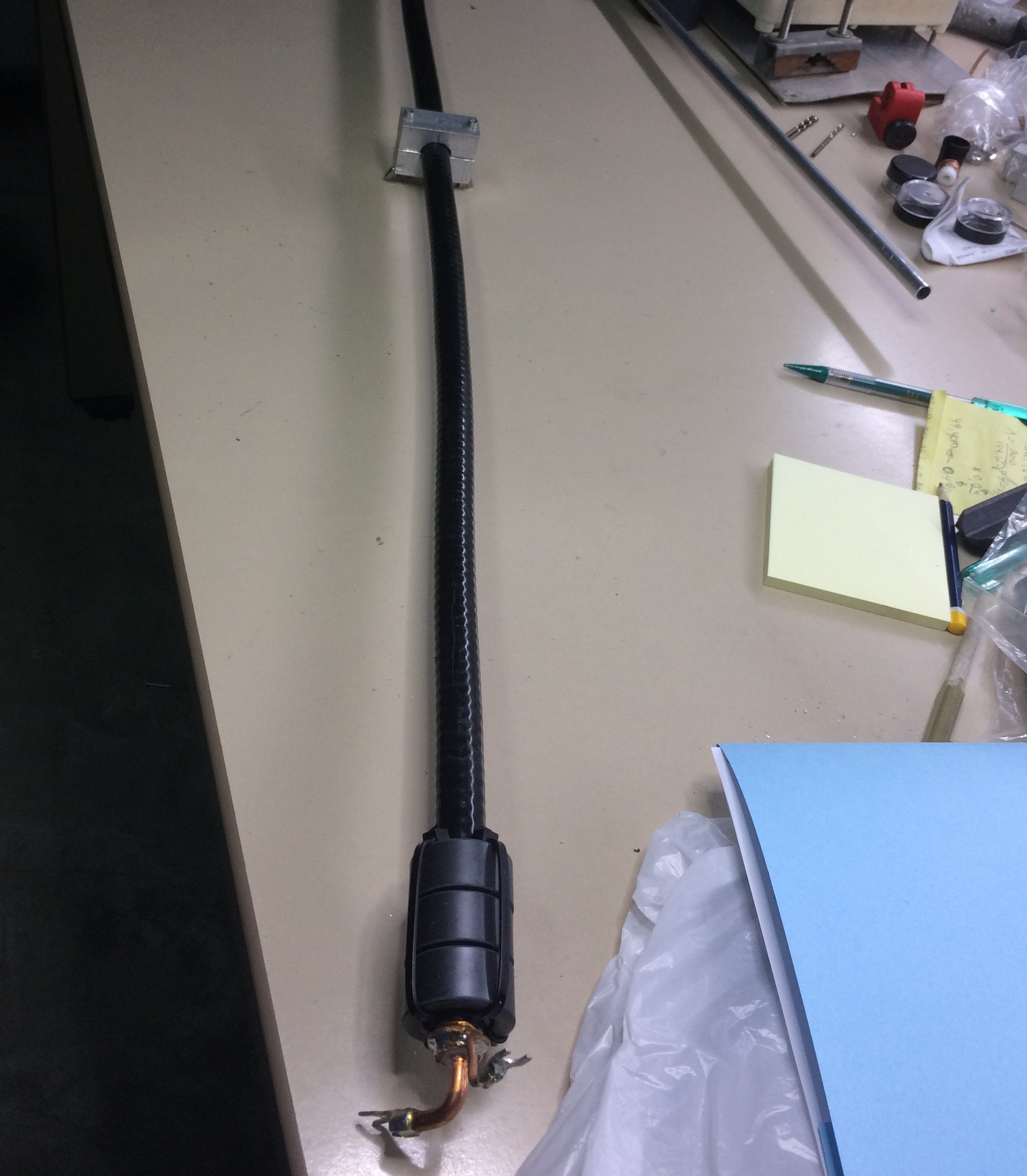
Sketch of Driver Cell

Note: DL2VL reports best match with the tips of the dipole bent backwards form the center line
by ~ 64 .. 69 mm = towards 217... 222 mm in the sketch above at a length of 979 mm*
*) with using carefully tuned 391 mm Ecoflex 10 + M3 soldering eyelets on as Quarterwave-to-gnd symmetrising line
Note: HA1VQ had to bring the ends of the bent Dipole quite a bit more straight again.
A good start would be to pick 255 mm as (b) for the tips instead of the 232 mm as per NEC geometry.
Sticking to the building scheme with semi-insulated on-boom elements and screw M3 and proposed BC + SBC
DL2VL reports a best RL at a distance of 69 mm from tips of DE to prolonged line of straight mid section.
• Bent DE Online Calculator as web app
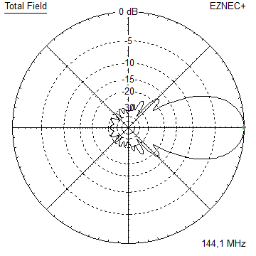
Pattern and VSWR Plots
Elevation and Azimuth plot at 144.1 MHz


Real world azimuth plot of the 2 x vertical stack of GTV 2-14w
.. done by DL2VL with PolarPlot V3.2.7 Software. Tnx Jörg!
The PolarPlot V3.2.7 Software by Bob, G4HFQ is free for non commercial use. Link to G4HFQ's website
Mind that this is not a free space plot but a 2 x vertically stacked array at 18 m AGL.


Note:
(1) the slight unsymmetry in the pattern plot is to a certain extend due to reflections on the test range,
as other here plotted Yagis show same regular distortion.
(2) Nulls go no deaper than -40 dB because PolarPlot v3.2.7 is not able to record below -40 dB.
VSWR and Return Loss plots - simulated with 4nec2

Note: due to the narrow band character of the Quarter Wave line made from H2010 trimmed to 144.2 MHz
(Q-factor) used for symmetrising, the Dip at 145 MHz is less intense then simulated.

Gain, F/B and F/R over Freq. - simulated with 4nec2

X-pol Details

Table Set 1: On Boom 8 mm Elements
There are two sets of tables provided:
(a) h- and v-plane for elements 8 mm on 25 x 25 mm boom
(b) h- and v-plane for elements 8 mm on 30 x 39 mm boom
Both use 520 mm or 1/ 4wl offset between h- and v-plane.
You may build with 25 mm throughout or any combination 25 and 30 mmm boom by picking the right corrected element length per plane and boom chosen.
This Yagi with 8 mm elements on a 25 x 25 mm boom with standard insulators
|
|
Ele. 8.0 mm DE 10 mm Boom 25 x 25 mm |
"Ready to saw and drill" data for mounting elements on boom with BC according DG7YBN for standard insulators as sold by Konni, Nuxcom, WiMo, 7arrays:
Includes an SBC of 1.70 mm


This Yagi with 8 mm elements on a 30 x 30 mm boom with standard insulators
|
|
Ele. 8.0 mm DE 10 mm Boom 30 x 30 mm |
"Ready to saw and drill" data for mounting elements on boom with BC according DG7YBN for standard insulators as sold by Konni, Nuxcom, WiMo, 7arrays:
Includes an SBC of 1.70 mm


Downloads
EZNEC file of this Yagi with 3/16 inch elements
EZNEC file of this Yagi with 5 mm elements
EZNEC file of this Yagi with 8 mm elements
EZNEC file of this Yagi as over stacked 4 bay (max. G/T)
Stacking

Stacking Dist. h-pol.    DL6WU     max. G/T
top-to-bottom           3.82 m      4.00 m
side-by-side            4.05 m      4.20 m
Elevation plot and data of 4 Yagi bay using DL6WU stacking distances

Gain vs. isotr. Rad.  22.15 dBi
Gain vs. Dipole       20.00 dBD
-3 dB H-plane         13.4 deg.
-3 dB E-plane         14.4 deg.
F/B                  -37.5 dB
F/R                  -29.1 dB
T_ant                218.8 K*
G/T                  -1.25 dB*

Theoretical numbers, no phasing line losses
nor imperfections caused by H-frame included
*) T_sky = 200 K, T_earth = 1000 K as in VE7BQH G/T table
Elevation and Azimuth plot and data of 4 Yagi bay using distances for max. G/T

Gain vs. isotr. Rad.  22.23 dBi
Gain vs. Dipole       20.08 dBD
-3 dB H-plane         13.0 deg.
-3 dB E-plane         13.8 deg.
F/B                  -36.1 dB
F/R                  -28.3 dB
T_ant                220.4 K*
G/T                  -1.20 dB*

Theoretical numbers, no phasing line losses
nor imperfections caused by H-frame included
*) T_sky = 200 K, T_earth = 1000 K as in VE7BQH G/T table
73, Hartmut, DG7YBN