-
• Main Page
- • Home
• Antennas - • 144 MHz
- Straight Dipole
144 MHz YagisYBN 2-9m: 4.5 m moderate band width, low Antenna Temperature, good willing 50 ohms direct feed Yagi - a straight DE version twin to the GTV 2-9m
Elevation Plot
- GTV 2-2mA 50 ohms direct feed 2 ele. Yagi with bent DE and potential as broad beam Contest Stack.
It can be used as back-to-back stack:
- GTV 2-4w1.0 m 144-146 MHz wide band width version of the Low Noise Yagi with bent DE as useful for satellite operation as for contesting thanks to high F/B and small volume of rear quadrants lobs in general.
Elevation Plot at 144.1 MHz

- GTV 2-5m1.6 m moderate to wide band width version of the Low Noise Yagi with bent DE as useful for satellite operation as for contesting thanks to high F/B and small volume of rear quadrants lobs in general.
Elevation Plot

- GTV 2-6m2.4 m moderate band width version of the low impedance, yet 50 ohms direct feed Low Noise Yagi with bent DE introduced in Dubus 1/2013
Elevation Plot
- GTV 2-7w2.7 m wide band width version of the low impedance, yet 50 ohms direct feed Low Noise Yagi with bent DE introduced in Dubus 1/2013
Elevation Plot
- GTV 2-7n3.1 m narrow band, max. G/T version of the low impedance, yet 50 ohms direct feed Low Noise Yagi with bent DE introduced in Dubus 1/2013
Elevation Plot
- GTV 2-8w3.7 m wide-band, still good G/T and nice F/B version of the low impedance, yet 50 ohms direct feed Low Noise Yagi with bent DE introduced in Dubus 1/2013
Elevation Plot
- GTV 2-8n3.8 m narrow band, max. G/T version of the low impedance, yet 50 ohms direct feed Low Noise Yagi with bent DE introduced in Dubus 1/2013
Elevation Plot

- GTV 2-9n4.3 m narrow band, balanced between low Antenna Temp. and G/T version of the low impedance, yet 50 ohms direct feed Low Noise Yagi with bent DE introduced in Dubus 1/2013
Elevation Plot

- GTV 2-9m4.5 m moderate band width, low Antenna Temp. version of the low impedance, yet 50 ohms direct feed Low Noise Yagi with bent DE introduced in Dubus 1/2013
Elevation Plot
- GTV 2-10LT5.1 m moderate band width, lowest Antenna Temp. version of the low impedance, yet 50 ohms direct feed Low Noise Yagi with bent DE introduced in Dubus 1/2013
Elevation Plot
- GTV 2-11LT6.0 m moderate band width, lowest Antenna Temp. version of the low impedance, yet 50 ohms direct feed Low Noise Yagi with bent DE introduced in Dubus 1/2013
Elevation Plot
- GTV 2-12m mk2Improved 6.8 m version of the low impedance, yet 50 ohms direct feed Low Noise Yagi with bent DE introduced in Dubus 1/2013
Elevation Plot:
- GTV 2-12n6.8 m narrow band version of the low impedance, yet 50 ohms direct feed Low Noise Yagi with bent DE introduced in Dubus 1/2013
Elevation Plot:
- GTV 2-13m7.5 m version of the low impedance, yet 50 ohms direct feed Low Noise Yagi with bent DE introduced in Dubus 1/2013
Elevation Plot:
- GTV 2-14w8.4 m version of the low impedance, yet 50 ohms direct feed Low Noise Yagi with bent DE introduced in Dubus 1/2013
Elevation Plot
- GTV 2-16w10 m version of the low impedance, yet 50 ohms direct feed Low Noise Yagi with bent DE introduced in Dubus 1/2013
Elevation Plot
- GTV 2-18w11.7 m version of the low impedance, yet 50 ohms direct feed Low Noise Yagi with bent DE introduced in Dubus 1/2013
Elevation Plot
- GTV 2-19m12.4 m version of the low impedance, yet 50 ohms direct feed Low Noise Yagi with bent DE introduced in Dubus 1/2013
Elevation Plot

- Straight Dipole
GTV 2-5m Yagi with bent Driven Element
For the given bandwidth this Yagi shows respectable low Antenna Temperature and a moderate gain for its length. I would not recommend this design for a contest stack in the first place because the azimuth plot is not as clean to the rear. This seems to be a challenge with whatever 5 element Yagi as soon as we put some bandwidth in. However this design is planned to serve as a xpol Yagi for satellite communication which can be built with less trouble. When cricular polarised the pattern looks fine for a wider 5 element.
There is a satellite band version, which when built as Cross Yagi, when circular poarised shows a respectable clear rear of the pattern for sch a boom length. With this xpol version the distance between v- and h-plane is a full 1/4 wavelength. So that feeding is uncomplicated via 2 same length 50 ohms coax cables and a power splitter for instance.
The bent DE (K6STI style) transforms to 50 ohms at feed point for direct feed. Design date of issue: 2025.01.24
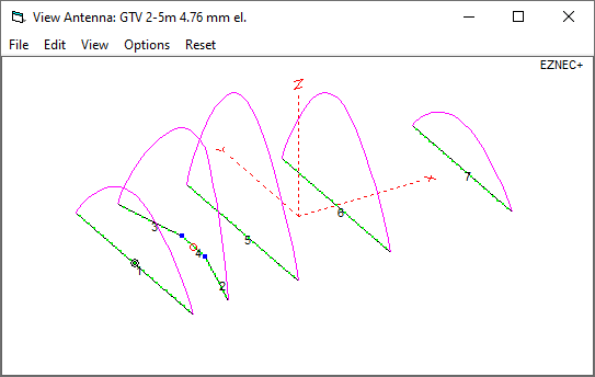
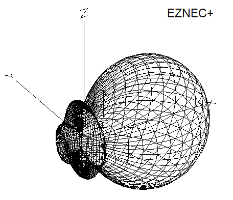
GTV 2-5m 3D pattern plot at 144.3 MHz
Performance Data
Specs: with 4.76 mm elements @ 144.3 MHz
Gain vs. isotr. Rad.  10.5 dBi
Gain vs. Dipole        8.4 dBD
-3 dB E-plane         44.6 deg.
-3 dB H-plane         52.8 deg.
F/B                  -32.2 dB
F/R                  -25.5 dB
Impedance               50 ohms
VSWR Band Width       1.06:1*
Mechan. Length        1617 mm plus offsets
Electr. Length        0.78 λ

Stacking Dist. h-pol. (144.3 MHz)
top-to-bottom         1.804 m or 5.9 ft
side-by-side          2.344 m or 7.7 ft

*) as in VE7BQH G/T table = at 145.00 MHz
How many VHF operators have been looking up this design since Febr. 2025?
Geometry
This Yagi with 8 mm elements on a 20 x 20 mm boom with standard insulators

|
Ele. 8.0 mm DE 10 mm Boom 20 x 20 mm |
|

"Ready to saw and drill" data for mounting elements on boom with BC according DG7YBN for standard insulators as sold by WiMo, Tino's Funkshop, HF-Kits NL, 7arrays:
Includes an SBC of 2.93 mm

The Drivers diameter is 10 mm.
The EZNEC model is done with Auto-Segmentation at 380 MHz

Ø 3/16 inch Elements, 3/8 inch Dipole - Through Boom - Dimensions (BC acc. SM5BSZ's BC.exe)
Imperial Boom 1"
|
This table is only valid for: Boom shape: square Boom dim: 1 x 1 inch Wall thickn.: 1.6 mm Holes in boom: 7.7 mm Offset rear: 40 mm Offset front: 40 mm |
Note: All the above include a "Segmentation Density Correction" (SBC) of 2.93 mm per element.
Note: with through Boom BC it is important to stick to the boom end offsets given below!
Read abt. the SBC here
![]()
Imperial Boom 1"
|
This table is only valid for: Boom shape: square Boom dim: 1 x 1 inch Wall thickn.: 1.6 mm Holes in boom: 7.7 mm Offset rear: 500 mm for foremast mounting Offset front: 40 mm |
Note: All the above include a "Segmentation Density Correction" (SBC) of 2.93 mm per element.
Note: with through Boom BC it is important to stick to the boom end offsets given below!
Read abt. the SBC here
![]()
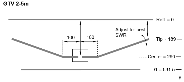
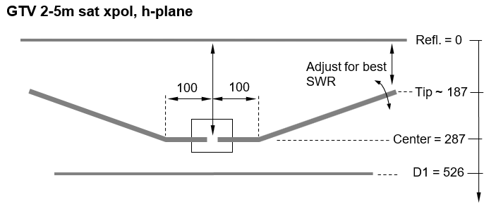
Sketch of Bent Dipole
Pattern and VSWR Plots
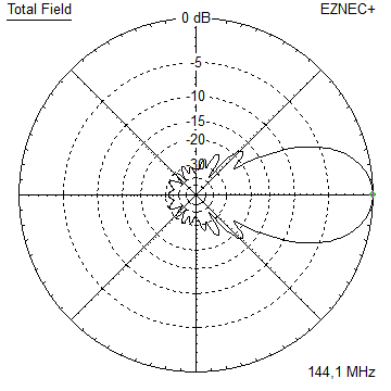
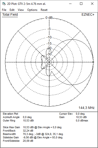
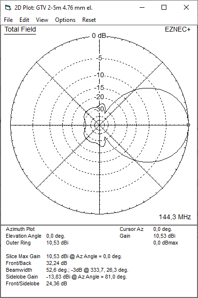
Elevation and Azimuth plot at 144.3 MHz, 4.76 mm element version:
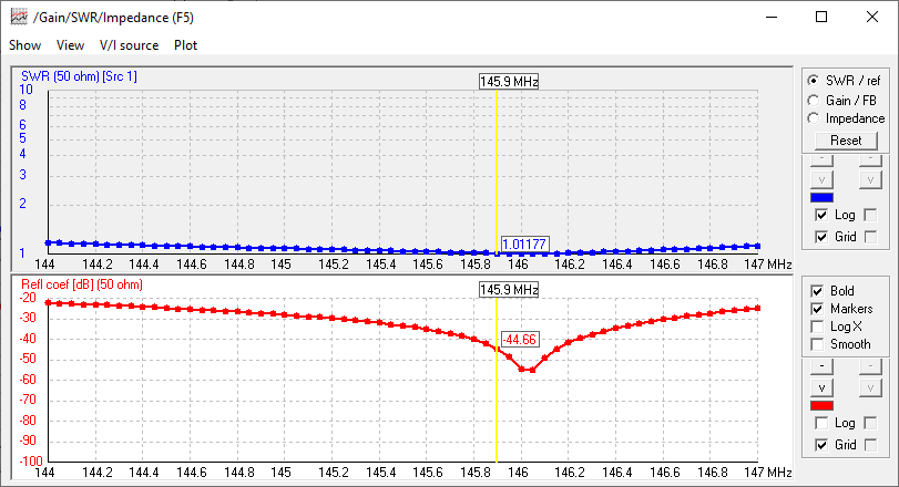
RL and SWR plots - simulated

Satellite xpol. Version
With this xpol version the distance between v- and h-plane is a full 1/4 wavelength. So that feeding is uncomplicated via 2 same length 50 ohms coax cables and a power splitter for instance. When bulding this, mind that the down planes differ slightly, see buiding table and sketch of bent dipole for v- and h-plane.
Circular polarised 3D pattern
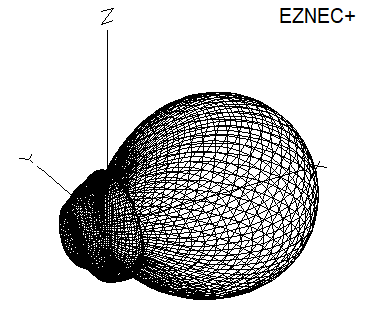

Circular polarised pattern with data, 145.8 MHz, elements 4.763 mm = 3/16 inch

VSWR and Return Loss (S11) with a bit of overhead when wet
Ø 3/16 inch Elements, 3/8 inch Dipole - Through Boom - Dimensions (BC acc. SM5BSZ's BC.exe),
offset element planes 514 mm = 1/4 wl on 145.9 MHz (Mind this refers to the two exiters, the dipoles distance).
Imperial Boom 1"
|
This table is only valid for: Boom shape: square Boom dim: 1 x 1 inch Wall thickn.: 1.6 mm Holes in boom: 7.7 mm Offset rear: 500 mm Offset front: 40 mm |
Note: All the above include a "Segmentation Density Correction" (SBC) of 2.93 mm per element.
Note: with through Boom BC it is important to stick to the boom end offsets given below!
Read abt. the SBC here
![]()
Sketches of Bent Dipoles

Downloads
None so far.
Stacking
Stacking at 1.80 m e, h for circular polarisation
which is slight understacking against distances per DL6WU formula.
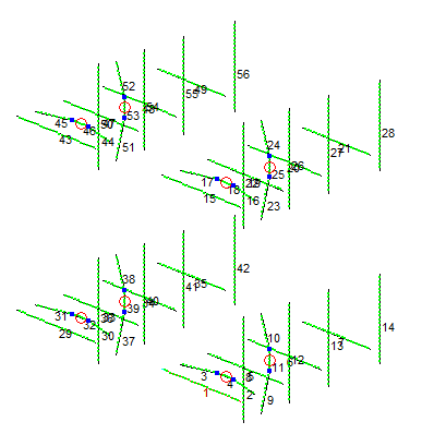
Plot and data of 4 stacked in H-configuration GTV 2-5m sat xpol
Antenna View & Elevation Pattern

73, Hartmut, DG7YBN