-
• Main Page
- • Home
• Antennas - • 144 MHz
- Straight Dipole
144 MHz YagisYBN 2-9m: 4.5 m moderate band width, low Antenna Temperature, good willing 50 ohms direct feed Yagi - a straight DE version twin to the GTV 2-9m
Elevation Plot
- GTV 2-2mA 50 ohms direct feed 2 ele. Yagi with bent DE and potential as broad beam Contest Stack.
It can be used as back-to-back stack:
- GTV 2-4w1.0 m 144-146 MHz wide band width version of the Low Noise Yagi with bent DE as useful for satellite operation as for contesting thanks to high F/B and small volume of rear quadrants lobs in general.
Elevation Plot at 144.1 MHz

- GTV 2-5m1.6 m moderate to wide band width version of the Low Noise Yagi with bent DE as useful for satellite operation as for contesting thanks to high F/B and small volume of rear quadrants lobs in general.
Elevation Plot

- GTV 2-6m2.4 m moderate band width version of the low impedance, yet 50 ohms direct feed Low Noise Yagi with bent DE introduced in Dubus 1/2013
Elevation Plot
- GTV 2-7w2.7 m wide band width version of the low impedance, yet 50 ohms direct feed Low Noise Yagi with bent DE introduced in Dubus 1/2013
Elevation Plot
- GTV 2-7n3.1 m narrow band, max. G/T version of the low impedance, yet 50 ohms direct feed Low Noise Yagi with bent DE introduced in Dubus 1/2013
Elevation Plot
- GTV 2-8w3.7 m wide-band, still good G/T and nice F/B version of the low impedance, yet 50 ohms direct feed Low Noise Yagi with bent DE introduced in Dubus 1/2013
Elevation Plot
- GTV 2-8n3.8 m narrow band, max. G/T version of the low impedance, yet 50 ohms direct feed Low Noise Yagi with bent DE introduced in Dubus 1/2013
Elevation Plot

- GTV 2-9n4.3 m narrow band, balanced between low Antenna Temp. and G/T version of the low impedance, yet 50 ohms direct feed Low Noise Yagi with bent DE introduced in Dubus 1/2013
Elevation Plot

- GTV 2-9m4.5 m moderate band width, low Antenna Temp. version of the low impedance, yet 50 ohms direct feed Low Noise Yagi with bent DE introduced in Dubus 1/2013
Elevation Plot
- GTV 2-10LT5.1 m moderate band width, lowest Antenna Temp. version of the low impedance, yet 50 ohms direct feed Low Noise Yagi with bent DE introduced in Dubus 1/2013
Elevation Plot
- GTV 2-11LT6.0 m moderate band width, lowest Antenna Temp. version of the low impedance, yet 50 ohms direct feed Low Noise Yagi with bent DE introduced in Dubus 1/2013
Elevation Plot
- GTV 2-12m mk2Improved 6.8 m version of the low impedance, yet 50 ohms direct feed Low Noise Yagi with bent DE introduced in Dubus 1/2013
Elevation Plot:
- GTV 2-12n6.8 m narrow band version of the low impedance, yet 50 ohms direct feed Low Noise Yagi with bent DE introduced in Dubus 1/2013
Elevation Plot:
- GTV 2-13m7.5 m version of the low impedance, yet 50 ohms direct feed Low Noise Yagi with bent DE introduced in Dubus 1/2013
Elevation Plot:
- GTV 2-14w8.4 m version of the low impedance, yet 50 ohms direct feed Low Noise Yagi with bent DE introduced in Dubus 1/2013
Elevation Plot
- GTV 2-16w10 m version of the low impedance, yet 50 ohms direct feed Low Noise Yagi with bent DE introduced in Dubus 1/2013
Elevation Plot
- GTV 2-18w11.7 m version of the low impedance, yet 50 ohms direct feed Low Noise Yagi with bent DE introduced in Dubus 1/2013
Elevation Plot
- GTV 2-19m12.4 m version of the low impedance, yet 50 ohms direct feed Low Noise Yagi with bent DE introduced in Dubus 1/2013
Elevation Plot

- Straight Dipole
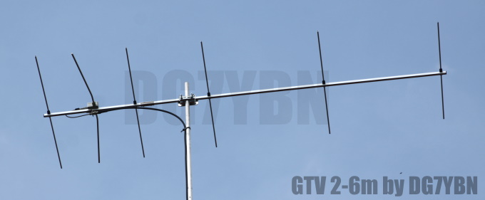
GTV 2-6m Yagi with bent Driven Element
This Yagi shows quite a low Antenna Temperature and a moderate gain for its length, which altogether leads to a good G/T number. It may serve as a contest stack or post stamp size EME 4-Yagi-Bay. Which may be useful especially under tough receiving conditions. The bent DE (K6STI style) transforms to 50 ohms at feed point for direct feed. Design date of issue: 2018.08.09
16 x GTV 2-6m xpol built by Bernd, DL7APV
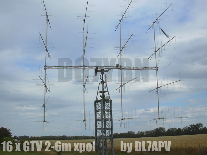
The 16 Yagis are built on 20 x 20 mm boom, 4 mm el. through boom held in place by 7arrays rivets.
Key data: 19.9 dBd (understacked at 2.1 x 1.95 m, sun noise 7 dB at an sfi of 70.
See full building and performance info on Bernds homepage
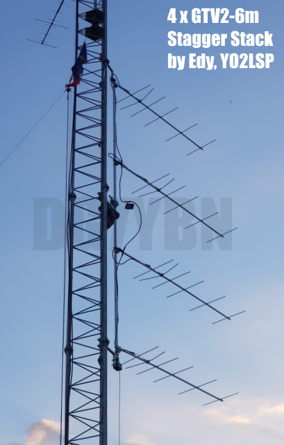
4 x GTV 2-6m Stagger Stack built by Edy, YO2LSP
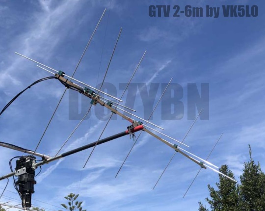
GTV 2-6m built by Mark, VK5LO
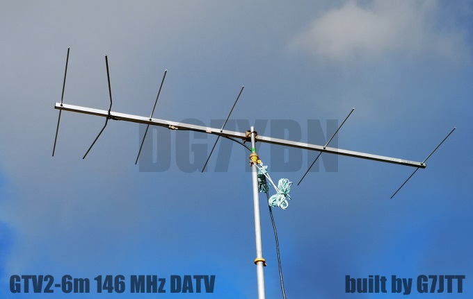
GTV 2-6m built by John, G7JTT
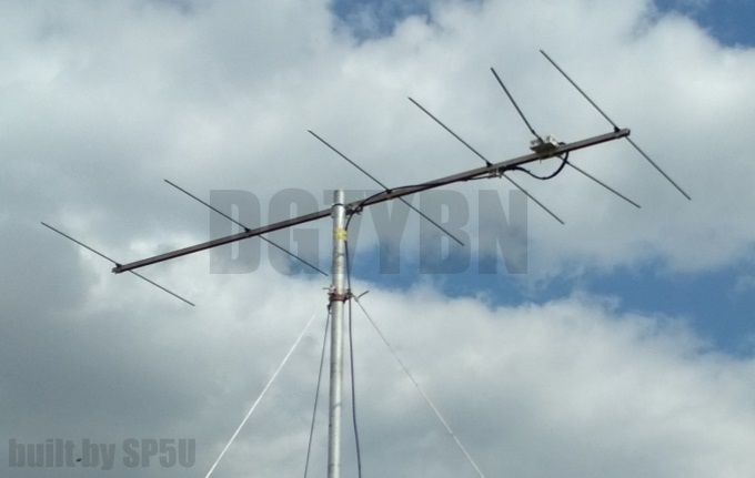
GTV 2-6m built by Mirek, SP5U
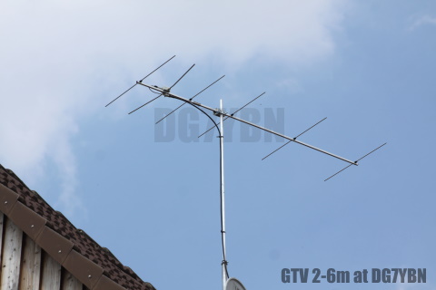
GTV 2-6m built by DG7YBN
Span Width of dipole = 985 mm
Gap Reflector - Tips of dipole = 216 mm
This Yagi is built on a boom 15 x 15 mm, elements 8 mm on standard holders + BC acc. DG7YBN.
Performance Data
Specs: with 8 mm elements @ 144.1 MHz
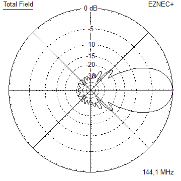
Gain vs. isotr. Rad.  11.9 dBi
Gain vs. Dipole        9.8 dBD
-3 dB E-plane         46.2 deg.
-3 dB H-plane         56.6 deg.
F/B                  -31.0 dB
F/R                  -22.7 dB
Impedance               50 ohms
VSWR Band Width       1.33:1 *
Mechan. Length        2370 mm
Electr. Length        1.14 λ

Stacking Dist. h-pol.
top-to-bottom         2.19 m or 7.2 ft
side-by-side          2.65 m or 8.7 ft

*) as in VE7BQH G/T table = at 145.00 MHz
How many VHF operators have been looking up this design since August 2018?
Geometry
Ø8 mm Elements - On Boom - Dimensions (BC acc. DG7YBN)
This Yagi with 8 mm elements on a 15 x 15 mm boom with standard insulators

|
Ele. 8.0 mm DE 10 mm Boom 15 x 15 mm |
"Ready to saw and drill" data for mounting elements on boom with BC according DG7YBN for standard insulators as sold by Konni, Nuxcom, WiMo, 7arrays:
Includes an SBC of 2.93 mm
This Yagi with 8 mm elements on a 20 x 20 mm boom with standard insulators
|
|
Ele. 8.0 mm DE 10 mm Boom 20 x 20 mm |
"Ready to saw and drill" data for mounting elements on boom with BC according DG7YBN for standard insulators as sold by Konni, Nuxcom, WiMo, 7arrays:
Includes an SBC of 2.93 mm
SegmentationBC = +2.93 mm = (144.7 MHz - 144.2 MHz) * 5.85 mm/MHz
BaseBC (20x20) = +3.90 mm for semi-insulated on boom
Total          = +6.83 mm
Note: element lengths for Ø 8 mm fit 5/16" too
On Boom 20 x 20 using SP6GWN Insulators which are a bit flatter
SegmentationBC = +2.93 mm = (144.7 MHz - 144.2 MHz) * 5.85 mm/MHz
BaseBC (20x20) = +3.90 mm for semi-insulated on boom
Add for Ins.   = +1.46 mm
Total          = +8.29 mm
Note: element lengths for Ø 8 mm fit 5/16" too
The Drivers diameter is 10 mm for all examples.
The EZNEC model is done with Auto-Segmentation at 400 MHz
This Yagi with 3/8 inch elements on a 1 x 1 inch boom with hydraulic clamps (like Stauff) or SM7DTT insulators

|
Ele. 3/8 inch or 9.53 mm DE 3/8 inch Boom 1 x 1 inch |
"Ready to saw and drill" data for mounting elements on boom with BC according DG7YBN for hydraulic clamps (like Stauff) or SM7DTT insulator:
Includes an SBC of 2.93 mm
![]()

Table 2: GTV 2-6m, 4 mm elements through boom:
"Ready to saw and drill" data for mounting elements through boom with BC according SM5BSZ's BC.exe:
Note: with through Boom BC it is important to stick to the boom end offsets given below!
Metric Boom 20 x 20 x 2 mm
|
This table is only valid for: Boom shape: square Boom dim: 20 x 20 mm Wall thickn.: 2.0 mm Holes in boom: 6.0 mm Offset rear: 40 mm Offset front: 40 mm |
|

Note: with through Boom BC it is important to stick to the boom end offsets given below!
Table 3: GTV 2-6m, 4.76 mm elements through boom:
Imperial Boom 1 x 1 inch x 1.6 mm
|
This table is only valid for: Boom shape: square Boom dim: 25.4 x 25.4 mm Wall thickn.: 1.6 mm Holes in boom: 7.5 mm Offset rear: 40 mm Offset front: 40 mm |
Note: with through Boom BC it is important to stick to the boom end offsets given below!
Sketch of Bent Dipole
Pattern and VSWR Plots
Elevation and Azimuth plot at 144.1 MHz
RL and SWR plots - simulated
Downloads
EZNEC file of this Yagi with 8 mm elements
xpol Details
General Hints for tuning xpol Yagis
(1) Set up the h-plane only
(2) Tune and plot Return Loss
See to make this single plane work fine, only then proceed.
(4) Add v-plane
(5) Replot h-plane
(6) If h-plane is still fine
(7) Mount the Yagi turned by 90 degr. so that freshly added v-plane is in h
(8) Tune and plot v-plane (in h now)
By measuring and trimming the v-plane in position horizontal we eliminate
possible unknown influences v to h mount for the while being. We would not
like to handle two unkowns at a time.
"Ready to saw and drill" data for mounting elements through boom with BC according SM5BSZ's BC.exe:
Note: with through Boom BC it is important to stick to the boom end offsets given below!
Table 2: GTV 2-6m xpol, 4 mm elements through boom:
Metric Boom 20 x 20 x 2 mm
|
This table is only valid for: Boom shape: square Boom dim: 20 x 20 mm Wall thickn.: 2.0 mm Holes in boom: 6.0 mm Offset rear: 750 / 860 mm Offset front: 150 / 40 mm |
|
Note: with through Boom BC it is important to stick to the boom end offsets given below!
Table 3: GTV 2-6m xpol, 4.76 mm elements through boom:
Imperial Boom 1 x 1 x 1/16 inch
|
This table is only valid for: Boom shape: square Boom dim: 1 x 1 inch Wall thickn.: 1.6 mm Holes in boom: 7.5 mm Offset rear: 750 / 860 mm Offset front: 150 / 40 mm |
Note: with through Boom BC it is important to stick to the boom end offsets given below!
Table 4: GTV 2-6m xpol, 3/8 inch or 9.53 mm elements on boom with hydraulic clamps (like Stauff) or SM7DTT insulators :
Imperial Boom 1 x 1 inch
|
|
Ele. 3/8 inch or 9.53 mm DE 3/8 inch Boom dim: 1 x 1 inch Offset rear: 750 / 860 mm Offset front: 150 / 40 mm |
Note: with through Boom BC it is important to stick to the boom end offsets given below!
Table 5: GTV 2-6m xpol, 145.5 MHz version, 8 mm elements on boom w. standard holders:
Metric Boom 20 x 20 mm
|
This table is only valid for: Boom shape: square Boom dim: 20 x 20 mm |
|

xpol SAT Details
Adaption of the GTV 2-6m to 145.8 MHz and element planes 1/4 wl apart for easy feed for Circular Polarisation.
Distance = 514 mm = 1/4 wl at 145.80 MHz
With that distance between the dipoles feeding both planes can be realised with equal length of 50 ohm coax and a 2-way power splitter
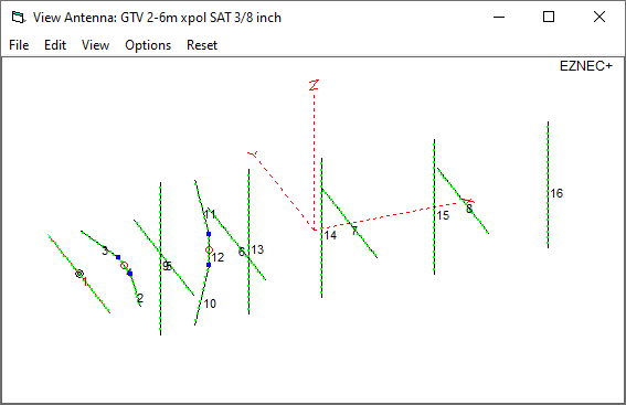
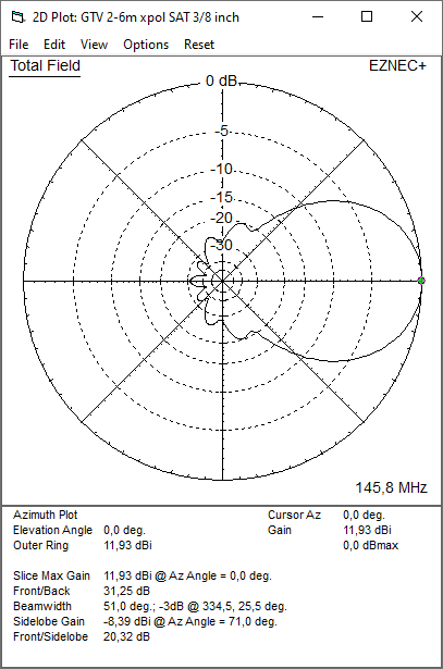
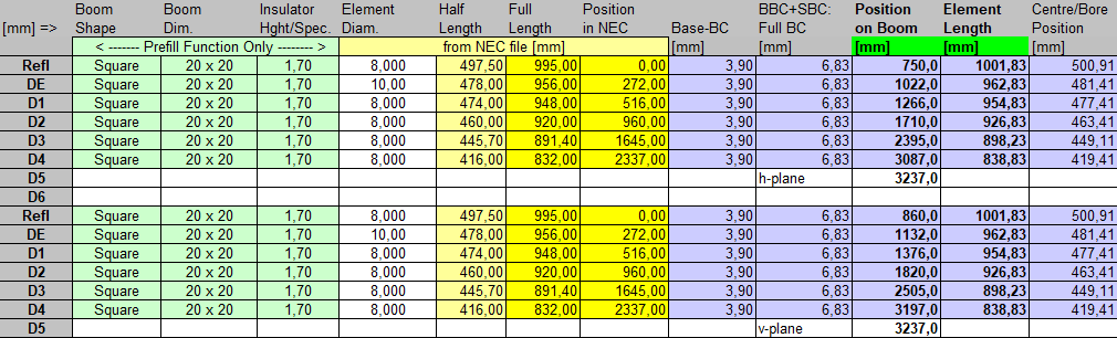
Table 6: GTV 2-6m xpol SAT, 145.8 MHz version, 3/8 inch elements on boom w. hyraulic clamps as holders:
Metric Boom 20 x 20 mm
|
This table is only valid for: Boom shape: square Boom dim: 1 x 1 inch |
|
![]()
• Shape and length of Dipole h-plane to v-plane differs slightly.
• Distance Refl. to Dipole h-plane to v-plane differs slightly.
• This geometry might also work with 10 mm elements and dipole.
You probably end up at approx. 145.7 MHz or shorten each ele. by roughly 0.6 mm per 100 kHz.
Stacking
Stacking Dist.    DL6WU Formula
E-plane               2.65 m or 8.7 ft
H-plane               2.19 m or 7.2 ft
Plot and data of 2 vertically stacked GTV 2-6m using DL6WU stacking distances
Antenna View & Elevation Pattern
Plot and data of 4 vertically stacked GTV 2-6m using DL6WU stacking distances
Antenna View, Elevation & Azimuth Pattern
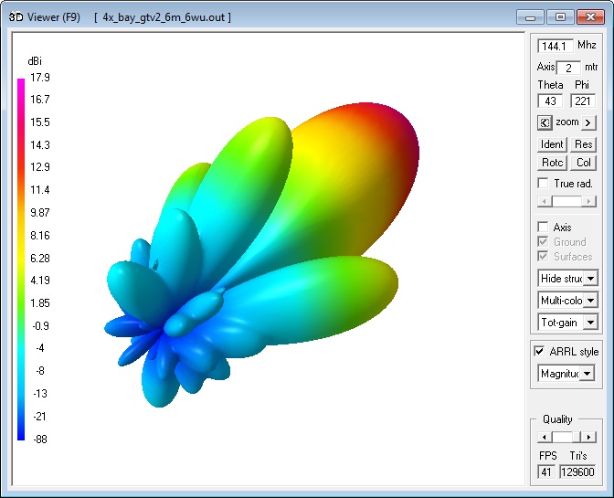
Plot and data of 4 bay of GTV 2-6m using DL6WU stacking distances
Elevation & Azimuth Pattern
AGTC_lite screenshot (Traditional Temps: Tsky = 200 K, Tearth = 1000 K)
AGTC_lite screenshot (Redefined Temps: Tsky = 287 K, Tearth = 5126 K acc. ITU)
Gain vs. isotr. Rad.  17.9 dBi
Gain vs. Dipole       15.7 dBD
-3 dB H-plane         25.2 deg.
-3 dB E-plane         20.6 deg.
F/B                  -33.0 dB
F/R                  -23.4 dB
T_los                  3.5 K
T_ant                498.6 K*  (236.1 K)
G/T                  -9.10 dB* (-5.85 K)
Theoretical numbers, no phasing line losses
nor imperfections caused by H-frame included
*) T_sky = 287 K, T_earth = 5126 K as in VE7BQH G/T table
2x 3x vert GTV 2-6m at 2.0 m vert, 2.4 m hor. stacking distances
16 x GTV 2-6m xpol ... 23.4 dBi: click to enlarge
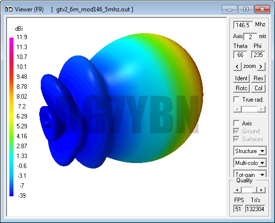
146.5 MHz DATV Version of the GTV 2-6m
This is a scaled to 146.5 MHz version of the GTV 2-6m.
Element lengths and positions are adapted to 146.5 MHz.
Hence the Pattern is same as for the 144 MHz Version
This Yagi with 8 mm elements on a 20 x 20 mm boom with standard insulators
|
|
Ele. 8.0 mm DE 10 mm Boom 20 x 20 mm |
"Ready to saw and drill" data for mounting elements on boom with BC according DG7YBN for standard insulators as sold by Konni, Nuxcom, WiMo, 7arrays:
Includes an SBC of 3.04 mm
This Yagi with 8 mm elements through a 25 x 25 x 1.5 mm boom
|
|
Ele. 8.0 mm DE 10.0 mm Boom 25 x 25 x 1.5 mm |
"Ready to saw and drill" data for mounting elements through boom with BC according SM5BSZ's BC.exe:
Note: with through Boom BC it is important to stick to the boom end offsets given below!
This table is only valid for:
Boom shape: square
Boom dim: 25 x 25 mm
Wall thickn.: 1.5 mm
Holes in boom: 10.0 mm
Offset rear: 40 mm
Offset front: 40 mm
Includes an SBC of 3.04 mm
Stacking Info 146.5 MHz DATV Version
Stacking Dist. h-pol.
top-to-bottom 2.16 m or 7.1 ft
side-by-side 2.61 m or 8.55 ft
73, Hartmut, DG7YBN