-
• Main Page
- • Home
• Antennas - • 144 MHz
- Straight Dipole
144 MHz YagisYBN 2-9m: 4.5 m moderate band width, low Antenna Temperature, good willing 50 ohms direct feed Yagi - a straight DE version twin to the GTV 2-9m
Elevation Plot
- GTV 2-2mA 50 ohms direct feed 2 ele. Yagi with bent DE and potential as broad beam Contest Stack.
It can be used as back-to-back stack:
- GTV 2-4w1.0 m 144-146 MHz wide band width version of the Low Noise Yagi with bent DE as useful for satellite operation as for contesting thanks to high F/B and small volume of rear quadrants lobs in general.
Elevation Plot at 144.1 MHz

- GTV 2-5m1.6 m moderate to wide band width version of the Low Noise Yagi with bent DE as useful for satellite operation as for contesting thanks to high F/B and small volume of rear quadrants lobs in general.
Elevation Plot

- GTV 2-6m2.4 m moderate band width version of the low impedance, yet 50 ohms direct feed Low Noise Yagi with bent DE introduced in Dubus 1/2013
Elevation Plot
- GTV 2-7w2.7 m wide band width version of the low impedance, yet 50 ohms direct feed Low Noise Yagi with bent DE introduced in Dubus 1/2013
Elevation Plot
- GTV 2-7n3.1 m narrow band, max. G/T version of the low impedance, yet 50 ohms direct feed Low Noise Yagi with bent DE introduced in Dubus 1/2013
Elevation Plot
- GTV 2-8w3.7 m wide-band, still good G/T and nice F/B version of the low impedance, yet 50 ohms direct feed Low Noise Yagi with bent DE introduced in Dubus 1/2013
Elevation Plot
- GTV 2-8n3.8 m narrow band, max. G/T version of the low impedance, yet 50 ohms direct feed Low Noise Yagi with bent DE introduced in Dubus 1/2013
Elevation Plot

- GTV 2-9n4.3 m narrow band, balanced between low Antenna Temp. and G/T version of the low impedance, yet 50 ohms direct feed Low Noise Yagi with bent DE introduced in Dubus 1/2013
Elevation Plot

- GTV 2-9m4.5 m moderate band width, low Antenna Temp. version of the low impedance, yet 50 ohms direct feed Low Noise Yagi with bent DE introduced in Dubus 1/2013
Elevation Plot
- GTV 2-10LT5.1 m moderate band width, lowest Antenna Temp. version of the low impedance, yet 50 ohms direct feed Low Noise Yagi with bent DE introduced in Dubus 1/2013
Elevation Plot
- GTV 2-11LT6.0 m moderate band width, lowest Antenna Temp. version of the low impedance, yet 50 ohms direct feed Low Noise Yagi with bent DE introduced in Dubus 1/2013
Elevation Plot
- GTV 2-12m mk2Improved 6.8 m version of the low impedance, yet 50 ohms direct feed Low Noise Yagi with bent DE introduced in Dubus 1/2013
Elevation Plot:
- GTV 2-12n6.8 m narrow band version of the low impedance, yet 50 ohms direct feed Low Noise Yagi with bent DE introduced in Dubus 1/2013
Elevation Plot:
- GTV 2-13m7.5 m version of the low impedance, yet 50 ohms direct feed Low Noise Yagi with bent DE introduced in Dubus 1/2013
Elevation Plot:
- GTV 2-14w8.4 m version of the low impedance, yet 50 ohms direct feed Low Noise Yagi with bent DE introduced in Dubus 1/2013
Elevation Plot
- GTV 2-16w10 m version of the low impedance, yet 50 ohms direct feed Low Noise Yagi with bent DE introduced in Dubus 1/2013
Elevation Plot
- GTV 2-18w11.7 m version of the low impedance, yet 50 ohms direct feed Low Noise Yagi with bent DE introduced in Dubus 1/2013
Elevation Plot
- GTV 2-19m12.4 m version of the low impedance, yet 50 ohms direct feed Low Noise Yagi with bent DE introduced in Dubus 1/2013
Elevation Plot

- Straight Dipole
GTV 2-18w Yagi with bent Driven Element
EME + SSB Yagi with much reserves in bandwidth.
I think a long Yagi like this needs a good standing wide band character to enable reproduction
when testing abilities due to handling a near 12 m boom beast are limited.
This long Yagi is balanced between gain and Antenna Temperature.
The bent DE (K6STI style) transforms from low impedance to 50 ohms at feed point for direct feed.
Date of first issue of design = 2019.11.15
Current Profile
Performance Data
Gain vs. isotr. Rad.  17.55 dBi
Gain vs. Dipole       15.4 dBD
-3 dB E-plane         25.6 deg.
-3 dB H-plane         26.8 deg.
F/B                  -35.3 dB
F/R                  -30.2 dB
Impedance               50 ohms
VSWR Band Width     1.08:1 *
Mechan. Length       11740 mm incl. 2 x 40 mm offset at boom ends
Electr. Length        5.60 λ

Stacking Dist. h-pol.
top-to-bottom         4.49 m or 14.7 ft
side-by-side          4.69 m or 15.4 ft

*) as in VE7BQH G/T table = at 145.00 MHz
Geometry

Table 1: GTV 2_18w, 8 mm elements on a 25 x 25 mm boom:
"Ready to saw and drill" data for mounting elements on boom with standard insulators. BC according DG7YBN:
|
Boom shape: square Boom dim: 25 x 25 mm |
|

Note: This includes a "Segmentation Density Correction" (SBC) of 1.17 mm
Table 2: GTV 2_18w, 8 mm elements on a tapered boom 20 x 20 and 25 x 25 mm boom:
"Ready to saw and drill" data for mounting elements on boom with standard insulators. BC according DG7YBN:
|
Boom shape: square Boom part 1: 20 x 20 mm Boom part 2: 25 x 25 mm Boom part 3: 20 x 20 mm |
|

Note: This includes a "Segmentation Density Correction" (SBC) of 1.17 mm
Sketch of Bent Dipole
This design has been viewed how often after the first built has been published in Nov. 2019?
Serving Suggestion
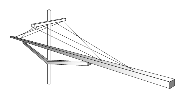
It is understood that it is vital for such a long beam of rather limited thickness
that we support it with a 3 dimensional stucture. Which might be produced by
the combination of a strut and two v-shape guy wires to front and back. With sufficent
stiffness to prevent the whole thing from shaking in wind gales which animate it to
vibrate in 1st or 3rd natural mode.
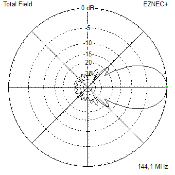
Pattern and VSWR Plots
Current distribution Elevation and Azimuth plot at 144.1 MHz

RL and SWR plot - simulated: 144.0 - 146.0 MHz
RL and SWR plot - simulated: 142.0 - 148.0 MHz
Downloads
One so far ...
X-pol Details
• Plane Offset is 584 mm.
Click on image to enlarge
• Stacking Distance is 4.59 m as average of h-pol. and v-pol. distances acc. DL6WU
Stacking
• DL6WU distances: 3D pattern simulation with 4nec2's 3D viewer
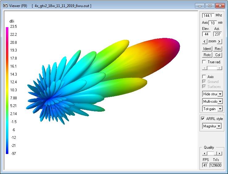
Stacking acc. DL6WU
Stacking Dist.    DL6WU Formula
E-plane               4.49 m or 14.7 ft
H-plane               4.69 m or 15.4 ft

X-pol Stacking Dist.
4.59 m each plane
Elevation and azimuth plot and data of 4 Yagi bay using DL6WU stacking distances

AGTC anyGTa 2lite screenshot at Tearth = 290 K, Tsky = 5400 K (residential area)
Gain vs. isotr. Rad.  23.45 dBi
Gain vs. Dipole       21.3 dBD
-3 dB H-plane  approx. 6   deg.
-3 dB E-plane  approx. 5.8 deg.
F/B                  -35.9 dB
F/R                  -31.9 dB
T_los                  6.5 K
T_ant                374.5 K*
G/T                  -2.28 dB*
Theoretical numbers, no phasing line losses
nor imperfections caused by H-frame included
*) T_sky = 290 K, T_earth = 5400 K as in VE7BQH G/T table for residential area
Same but understacked at DL6WU -12 percent
Stacking Dist.    DL6WU Formula
E-plane               4.49 m x 0.88 = 3.95 m
H-plane               4.69 m x 0.88 = 4.13 m

X-pol Stacking Dist.
4.04 m each plane
Same but overstacked at DL6WU +8 percent
Stacking Dist.    DL6WU Formula
E-plane               4.49 m x 1.08 = 4.85 m
H-plane               4.69 m x 1.08 = 5.06 m

X-pol Stacking Dist.
4.04 m each plane
in a fictive Antenna G/Ta table:
73, Hartmut, DG7YBN