-
• Main Page
- • Home
• Antennas - • 144 MHz
- Straight Dipole
144 MHz YagisYBN 2-9m: 4.5 m moderate band width, low Antenna Temperature, good willing 50 ohms direct feed Yagi - a straight DE version twin to the GTV 2-9m
Elevation Plot
- GTV 2-2mA 50 ohms direct feed 2 ele. Yagi with bent DE and potential as broad beam Contest Stack.
It can be used as back-to-back stack:
- GTV 2-4w1.0 m 144-146 MHz wide band width version of the Low Noise Yagi with bent DE as useful for satellite operation as for contesting thanks to high F/B and small volume of rear quadrants lobs in general.
Elevation Plot at 144.1 MHz

- GTV 2-5m1.6 m moderate to wide band width version of the Low Noise Yagi with bent DE as useful for satellite operation as for contesting thanks to high F/B and small volume of rear quadrants lobs in general.
Elevation Plot

- GTV 2-6m2.4 m moderate band width version of the low impedance, yet 50 ohms direct feed Low Noise Yagi with bent DE introduced in Dubus 1/2013
Elevation Plot
- GTV 2-7w2.7 m wide band width version of the low impedance, yet 50 ohms direct feed Low Noise Yagi with bent DE introduced in Dubus 1/2013
Elevation Plot
- GTV 2-7n3.1 m narrow band, max. G/T version of the low impedance, yet 50 ohms direct feed Low Noise Yagi with bent DE introduced in Dubus 1/2013
Elevation Plot
- GTV 2-8w3.7 m wide-band, still good G/T and nice F/B version of the low impedance, yet 50 ohms direct feed Low Noise Yagi with bent DE introduced in Dubus 1/2013
Elevation Plot
- GTV 2-8n3.8 m narrow band, max. G/T version of the low impedance, yet 50 ohms direct feed Low Noise Yagi with bent DE introduced in Dubus 1/2013
Elevation Plot

- GTV 2-9n4.3 m narrow band, balanced between low Antenna Temp. and G/T version of the low impedance, yet 50 ohms direct feed Low Noise Yagi with bent DE introduced in Dubus 1/2013
Elevation Plot

- GTV 2-9m4.5 m moderate band width, low Antenna Temp. version of the low impedance, yet 50 ohms direct feed Low Noise Yagi with bent DE introduced in Dubus 1/2013
Elevation Plot
- GTV 2-10LT5.1 m moderate band width, lowest Antenna Temp. version of the low impedance, yet 50 ohms direct feed Low Noise Yagi with bent DE introduced in Dubus 1/2013
Elevation Plot
- GTV 2-11LT6.0 m moderate band width, lowest Antenna Temp. version of the low impedance, yet 50 ohms direct feed Low Noise Yagi with bent DE introduced in Dubus 1/2013
Elevation Plot
- GTV 2-12m mk2Improved 6.8 m version of the low impedance, yet 50 ohms direct feed Low Noise Yagi with bent DE introduced in Dubus 1/2013
Elevation Plot:
- GTV 2-12n6.8 m narrow band version of the low impedance, yet 50 ohms direct feed Low Noise Yagi with bent DE introduced in Dubus 1/2013
Elevation Plot:
- GTV 2-13m7.5 m version of the low impedance, yet 50 ohms direct feed Low Noise Yagi with bent DE introduced in Dubus 1/2013
Elevation Plot:
- GTV 2-14w8.4 m version of the low impedance, yet 50 ohms direct feed Low Noise Yagi with bent DE introduced in Dubus 1/2013
Elevation Plot
- GTV 2-16w10 m version of the low impedance, yet 50 ohms direct feed Low Noise Yagi with bent DE introduced in Dubus 1/2013
Elevation Plot
- GTV 2-18w11.7 m version of the low impedance, yet 50 ohms direct feed Low Noise Yagi with bent DE introduced in Dubus 1/2013
Elevation Plot
- GTV 2-19m12.4 m version of the low impedance, yet 50 ohms direct feed Low Noise Yagi with bent DE introduced in Dubus 1/2013
Elevation Plot

- Straight Dipole
GTV 2-11 LT Yagi with bent Driven Element
This Yagi shows quite a low Antenna Temperature and a moderate gain for its length, which altogether is leading to a good G/T number. It may serve as a contest stack or medium size EME 4-Yagi-Bay, especially under tough RXing conditions.The bent DE (K6STI style) transforms to 50 ohms at feed point for direct feed.
This Yagi-Uda design makes maximum use of a 6.0 m off the shelf aluminium tube as boom without compromising on any design parameters to squeeze the electrical length into the given 6.0 m.
2 x GTV2-11LT at DP0GVN, Antartic Research Station, built by DL2ALY

Photos on courtesy of DL2ALY. Tnx Alex!
DP0GVN is a club station at the German Research Station "Neumayer III" in Dronning Maud Land, Antarctica. QRA-Loc.. IB59UI
See https://www.qrz.com/db/DP0GVN
and https://www.qrz.com/db/DL2ALY
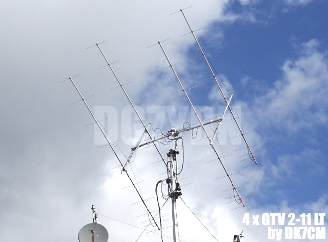
4 x GTV2-11LT by DK7CM
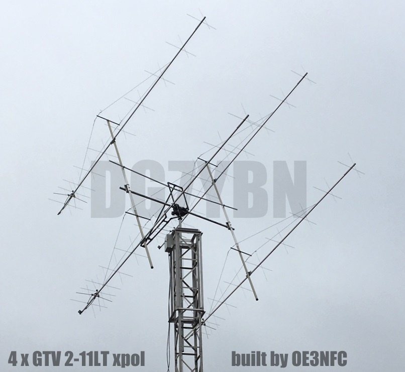
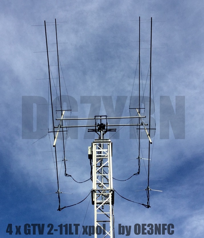
4 x GTV2-11LT xpol at OE3NFC
These Yagi sare built on 25 x 25 mm boom using 4 mm elements with SM5BSZ BC.exe Boom Correction,
held by 7arrays 4x6 mm insulators. Click Images to enlarge


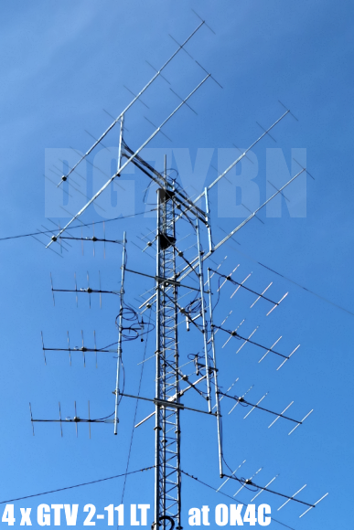
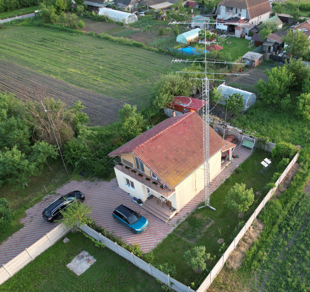
4 x GTV2-11LT at OK4C club station QTH
2 x vertical GTV2-11LT above a GTV 70-25m, all built by Edy, YO2LSP
These 2 Yagis are built on boom 25 x 25 mm using 10 mm elements (click onto images to enlarge:

Edy, YO2LSP: "I finish and tested the new setup. It`s working great! New personal records for this location." ... tnx Edy!
2 x vertical GTV2-11LT built by YO2LSP, used in 2020 IARU ctest by YO5LD

who succeeded an excellent results for the YO position. - 413 QSO`s , ODX - DA0FF @ 1028 km, Total: 192.955 points.
The antenna works fantastic, in special 2x11 element system. Thank you for your work." ... tnx Edy!
GTV2-11LT built by Sergey, R7MU


Performance Data
Specs: with 8 mm elements @ 144.1 MHz
Gain vs. isotr. Rad.  15.1 dBi
Gain vs. Dipole       12.9 dBD
-3 dB E-plane         34.1 deg.
-3 dB H-plane         37.2 deg.
F/B                  -35.1 dB
F/R                  -29.7 dB
Impedance               50 ohms
VSWR Band Width     1.26:1 *
Mechan. Length        5920 mm
Electr. Length        2.85 λ

Stacking Dist. h-pol.
top-to-bottom         3.26 m
side-by-side          3.55 m

*) as in VE7BQH G/T table = at 145.00 MHz
2x GTV2-11LT xpol at HB9W

GTV2-11LT and GTV70-25m built by PA2CV

How many VHF operators have been looking up this design since May 2016?
Geometry


Ø8 mm Elements - On Boom - Dimensions (BC acc. DG7YBN)
		Refl	 DE(b)	 DE(a)	D1	D2	D3	D4	D5	D6	D7	D8	D9
Pos. 		0	 247	 285	420	680	1171	1817	2594	3434	4279	5130	5920
Boom 20x20 mm	1026.2	(992.2)	(100)	961.2	954.2	928.2	912.2	895.2	885.2	876.2	864.2	838.2
Boom 25x25 mm	1029.9	(995.9)	(100)	964.9	957.9	931.9	915.9	898.9	888.9	879.9	867.9	841.9
SegmentationBC = +2.3 mm = (144.7 MHz - 144.3 MHz) * 5.85 mm/MHz
BaseBC         = +3.9 mm for semi-insulated on boom (20 x 20 mm), 7.6 mm (25 x 25 mm)
Total          = +6.2 mm (20 x 20 mm), +9.9 mm (25 x 25 mm)
Note: element lengths for Ø 8 mm fit 5/16" too
Ø10 mm Elements - On Boom - Dimensions (BC acc. DG7YBN)
		Refl	 DE(b)	 DE(a)	D1	D2	D3	D4	D5	D6	D7	D8	D9
Pos. 		0	 247	 285	420	680	1171	1817	2594	3434	4279	5130	5920
Boom 20x20 mm	1020.2	(992.2)	(100)	956.2	948.2	920.2	904.2	886.2	876.2	866.2	855.2	828.2
Boom 25x25 mm	1023.9	(995.9)	(100)	959.9	951.9	923.9	907.9	889.9	879.9	869.9	858.9	831.9

Total-BC       = +6.2 mm (20 x 20 mm), +9.9 mm (25 x 25 mm)
For Elements 10 mm on a 25 x 25 mm boom
This table is only valid for:
Boom shape: square
Boom dim: 25 x 25 mm
Offset rear: 40 mm
Offset front: 40 mm
Note: This includes a "Segmentation Density Correction" (SBC) of 2.3 mm

The Drivers diameter is 10 mm for all examples.
The EZNEC model is done with Auto-Segmentation at 380 MHz
"Ready to saw and drill" data for mounting elements through boom with BC according SM5BSZ's BC.exe:
Note: with through Boom BC it is important to stick to the boom end offsets given below!
For Elements 3/16 inch through a 1 x 1 inch boom
This table is only valid for:
Boom shape: square
Boom dim: 1 x 1 in
Wall thickn.: 1/16 in
Holes in boom: 9.5 mm
Offset rear: 40 mm
Offset front: 40 mm
Note: This includes a "Segmentation Density Correction" (SBC) of 2.3 mm
Read abt. the SBC here
![]()

For Elements 6.0 mm through a 25 x 25 mm boom
This table is only valid for:
Boom shape: square
Boom dim: 25 x 25 mm
Wall thickn.: 1.5 mmn
Holes in boom: 8.0 mm
Offset rear: 40 mm
Offset front: 40 mm
Note: This includes a "Segmentation Density Correction" (SBC) of 2.3 mm

For Elements 6.0 mm through a 1 x 1 inch boom
This table is only valid for:
Boom shape: square
Boom dim: 1 x 1 inch
Wall thickn.: 1/16 in = 1.6 mmn
Holes in boom: 8.0 mm
Offset rear: 40 mm
Offset front: 40 mm
Note: This includes a "Segmentation Density Correction" (SBC) of 2.3 mm
![]()
For Elements 6.0 mm through a TAPERED BOOM 20 x 20 mm > 25 x 25 mm > 20 x 20 mm boom
This table is only valid for:
Boom shape: square
Boom dim: 20 x 20 mm > 25 x 25 mm > 20 x 20 mm
Wall thickn.: 1.5 mmn
Holes in boom: 8.0 mm
Offset rear: 40 mm
Offset front: 40 mm
Note: This includes a "Segmentation Density Correction" (SBC) of 2.3 mm

Sketch of Bent Dipole

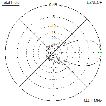
Pattern and VSWR Plots
Current distribution Elevation and Azimuth plot at 144.1 MHz


RL and SWR plot - simulated

GTV2-11LT Return Loss Plot by PA2CV


X-pol Details

xpol builders table 1: GTV 2-11LT, 4.0 mm elements through boom:
"Ready to saw and drill" data for mounting elements through boom with BC according SM5BSZ's BC.exe:
Note: with through Boom BC it is important to stick to the boom end offsets given below!
This table is only valid for:
Boom shape: square
Boom dim: 25 x 25 mm
Wall thickn.: 2.0 mm
Holes in boom: 6.0 mm
Offset rear: 500 mm resp. 570 mm
Offset front: 110 mm resp. 40 mm
Note: This includes a "Segmentation Density Correction" (SBC) of 2.3 mm
Read abt. the SBC here
Elements in h-plane


GTV 2-11 LT xpol with 3/16 inch elements
This table is only valid for:
Boom shape: square
Boom dim: 1-1/4 x 1-1/4 inch
Wall thickn.: 1.2 mm
Holes in boom: 9.5 mm
Offset rear: 500 mm resp. 570 mm
Offset front: 110 mm resp. 40 mm
Note: This includes a "Segmentation Density Correction" (SBC) of 2.3 mm
Read abt. the SBC here
Elements in h-plane


Same conditions boom but for Elements 1/4 inch
Elements in h-plane


Downloads
EZNEC file of this Yagi with 8 mm elements
EZNEC file of this Yagi with 4 mm elements
Stacking


Stacking Dist.    DL6WU Formula
E-plane               3.538 m
H-plane               3.261 m
Plot and data of 4 Yagi bay using DL6WU stacking distances
Elevation Pattern

TANT screenshot

Gain vs. isotr. Rad.  21.0 dBi
Gain vs. Dipole       18.8 dBD
-3 dB H-plane         15.4 deg.
-3 dB E-plane         16.8 deg.
F/B                  -39.6 dB
F/R                  -32.8 dB
T_los                  4.5 K
T_ant                222.0 K*
G/T                  -2.51 dB*
Theoretical numbers, no phasing line losses
nor imperfections caused by H-frame included
*) T_sky = 200 K, T_earth = 1000 K as in VE7BQH G/T table
73, Hartmut, DG7YBN