-
• Main Page
- • Home
• Antennas - • 144 MHz
- Straight Dipole
144 MHz YagisYBN 2-9m: 4.5 m moderate band width, low Antenna Temperature, good willing 50 ohms direct feed Yagi - a straight DE version twin to the GTV 2-9m
Elevation Plot
- GTV 2-2mA 50 ohms direct feed 2 ele. Yagi with bent DE and potential as broad beam Contest Stack.
It can be used as back-to-back stack:
- GTV 2-4w1.0 m 144-146 MHz wide band width version of the Low Noise Yagi with bent DE as useful for satellite operation as for contesting thanks to high F/B and small volume of rear quadrants lobs in general.
Elevation Plot at 144.1 MHz

- GTV 2-5m1.6 m moderate to wide band width version of the Low Noise Yagi with bent DE as useful for satellite operation as for contesting thanks to high F/B and small volume of rear quadrants lobs in general.
Elevation Plot

- GTV 2-6m2.4 m moderate band width version of the low impedance, yet 50 ohms direct feed Low Noise Yagi with bent DE introduced in Dubus 1/2013
Elevation Plot
- GTV 2-7w2.7 m wide band width version of the low impedance, yet 50 ohms direct feed Low Noise Yagi with bent DE introduced in Dubus 1/2013
Elevation Plot
- GTV 2-7n3.1 m narrow band, max. G/T version of the low impedance, yet 50 ohms direct feed Low Noise Yagi with bent DE introduced in Dubus 1/2013
Elevation Plot
- GTV 2-8w3.7 m wide-band, still good G/T and nice F/B version of the low impedance, yet 50 ohms direct feed Low Noise Yagi with bent DE introduced in Dubus 1/2013
Elevation Plot
- GTV 2-8n3.8 m narrow band, max. G/T version of the low impedance, yet 50 ohms direct feed Low Noise Yagi with bent DE introduced in Dubus 1/2013
Elevation Plot

- GTV 2-9n4.3 m narrow band, balanced between low Antenna Temp. and G/T version of the low impedance, yet 50 ohms direct feed Low Noise Yagi with bent DE introduced in Dubus 1/2013
Elevation Plot

- GTV 2-9m4.5 m moderate band width, low Antenna Temp. version of the low impedance, yet 50 ohms direct feed Low Noise Yagi with bent DE introduced in Dubus 1/2013
Elevation Plot
- GTV 2-10LT5.1 m moderate band width, lowest Antenna Temp. version of the low impedance, yet 50 ohms direct feed Low Noise Yagi with bent DE introduced in Dubus 1/2013
Elevation Plot
- GTV 2-11LT6.0 m moderate band width, lowest Antenna Temp. version of the low impedance, yet 50 ohms direct feed Low Noise Yagi with bent DE introduced in Dubus 1/2013
Elevation Plot
- GTV 2-12m mk2Improved 6.8 m version of the low impedance, yet 50 ohms direct feed Low Noise Yagi with bent DE introduced in Dubus 1/2013
Elevation Plot:
- GTV 2-12n6.8 m narrow band version of the low impedance, yet 50 ohms direct feed Low Noise Yagi with bent DE introduced in Dubus 1/2013
Elevation Plot:
- GTV 2-13m7.5 m version of the low impedance, yet 50 ohms direct feed Low Noise Yagi with bent DE introduced in Dubus 1/2013
Elevation Plot:
- GTV 2-14w8.4 m version of the low impedance, yet 50 ohms direct feed Low Noise Yagi with bent DE introduced in Dubus 1/2013
Elevation Plot
- GTV 2-16w10 m version of the low impedance, yet 50 ohms direct feed Low Noise Yagi with bent DE introduced in Dubus 1/2013
Elevation Plot
- GTV 2-18w11.7 m version of the low impedance, yet 50 ohms direct feed Low Noise Yagi with bent DE introduced in Dubus 1/2013
Elevation Plot
- GTV 2-19m12.4 m version of the low impedance, yet 50 ohms direct feed Low Noise Yagi with bent DE introduced in Dubus 1/2013
Elevation Plot

- Straight Dipole
GTV 2-9n Yagi with bent Driven Element
EME + SSB narrow bandwidth version ... strictly G/T breeding
This medium length Yagi is balanced between gain and Antenna Temperature. In comparison to most of the entries with exceptional G/T around 2.09 wl in the 144 MHz VE7BQH G/T table its T_ant is approximately 5 ... 10 K lower. Thus it may be very useful in difficult RXing scenarios like contests or EME from within a city with a small size 4-Yagi-Bay only. The bent DE (K6STI style) transforms from low impedance to 50 ohms at feed point for direct feed.
GTV 2-9n built by members of OM3KSI, Radioclub Leteckej fakulty

Image: OM3KSI
GTV 2-9n QRO version built by DG7YBN @ 7arrays.com
A GTV 2-9n built on 25x25 mm boom with 12 mm Dipole, Symmetrising Line from Cellflex LCF12-50J and DIN 7/16 bushing.
See details of > 1hp plus Symmetrising Line and Return Loss plot below

GTV 2-9n X-pol QRO version built by DG7YBN @ 7arrays.com. For details on feeds, see here

Current Profile

Performance Data
Gain vs. isotr. Rad.  14.0 dBi
Gain vs. Dipole       11.9 dBD
-3 dB E-plane         37.8 deg.
-3 dB H-plane         42.2 deg.
F/B                  -26.1 dB
F/R                  -25.4 dB
Impedance               50 ohms
VSWR Band Width     1.57:1 *
Mechan. Length        4320 mm
Electr. Length        2.08 λ

Stacking Dist. h-pol.
top-to-bottom         2.89 m
side-by-side          3.21 m

*) as in VE7BQH G/T table = at 145.00 MHz
Geometry
SegmentationBC = +2.3 mm = (144.6 MHz - 144.2 MHz) * 5.85 mm/MHz
BaseBC (20x20) = +3.9 mm for semi-insulated on boom
Total = +6.2 mm
Note: element lengths for Ø 8 mm fit 5/16" too
The Drivers diameter is 10 mm for all examples. Use EZNEC's Auto-Segmentation at 380 MHz.

Table 1: GTV 2-9n, 6 mm elements on a 20 x 20 mm boom:
"Ready to saw and drill" data for elements on boom with BC acc. DG7YBN for standard insulators as sold by WiMo, Tino's Funkshop, HF Kits.nl, 7arrays:
|
Boom shape: square Boom: 20 x 20 mm Offset rear: 40 mm Offset front: 40 mm |
|

Note: This includes a "Segmentation Density Correction" (SBC) of 2.05 mm

Table 2: GTV 2-9n, 8 mm elements on a 20 x 20 mm boom:
"Ready to saw and drill" data for elements on boom with BC acc. DG7YBN for standard insulators as sold by WiMo, Tino's Funkshop, HF Kits.nl, 7arrays:
|
Boom shape: square Boom: 20 x 20 mm Offset rear: 40 mm Offset front: 40 mm |
|
Note: This includes a "Segmentation Density Correction" (SBC) of 2.28 mm

Table 3: GTV 2-9n, 8 mm elements on a 25 x 25 mm boom:
"Ready to saw and drill" data for elements on boom with BC acc. DG7YBN for standard insulators as sold by WiMo, Tino's Funkshop, HF Kits.nl, 7arrays:
|
Boom shape: square Boom: 25 x 25 mm Offset rear: 40 mm Offset front: 40 mm |
|

Note: This includes a "Segmentation Density Correction" (SBC) of 2.28 mm


Table 3: GTV 2-9n, Imperial Measures 3/16" or 4.763 mm elements through a 1 x 1" boom:
"Ready to saw and drill" data for mounting elements through boom with BC according SM5BSZ's BC.exe:
Note: with through Boom BC it is important to stick to the boom end offsets given below!
|
This table is only valid for: Boom shape: square Boom dim: 1 x 1" or 25.4 x 25.4 mm Wall thickn.: 1.6 mm Holes in boom: 7.9 mm Offset rear: 40 mm Offset front: 40 mm |
|

Note: This includes a "Segmentation Density Correction" (SBC) of 2.28 mm
![]()
Sketch of Bent Dipole

This design has been viewed how often after the first built has been published in Apr. 2017?
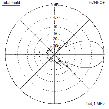
Pattern and VSWR Plots
Elevation and Azimuth plot at 144.1 MHz, 8 mm elements


RL and SWR plot - simulated


• 130 - 150 MHz real world plot of GTV 2-9n QRO version (mind that the 1/4 wl line is frequency selective, hence the 138 MHz bit is less deep)

• Plotted Return Loss of GTV 2-9n X-pol QRO Version, V-Plane mounted horizontally (due to metal pole)

QRO Quarterwave Line with Cellflex 1/2 inch coax and 7/16 connector: View on Dipole Side - to be sealed with Spinner Plast 2000

Connector Side: View into the DIN 7/16 bushing

GTV 2-9n X-pol QRO Version Driver Cell

Note the double reflector in one plane only. The reason for this is nothing but handling the Cellflex LCF12-50J
quarterwave lines of both planes to the rear end of the Yagi without interfering with the other plans reflector.
Details on this QRO Quarterwave Line, see here
Downloads
EZNEC file of this Yagi with 8 mm elem.
EZNEC file of this Yagi as xpol with 8 mm elem. on 25 x 25 mm Boom
X-pol Details
• Plane Offset is 220 mm.
• Reflectors are same length for all: 1029.9 mm incl. SBC and BC for on 25 x 25 mm Boom
• Distance Mid-DE to Double Refl. (h-plane) is 285 mm
• Offset Refl. (h-plane) to Mid-Boom is +/- 100 mm
• Distance Mid-DE to Single Refl. (v-plane) is 310 mm

Stacking


Stacking Dist.    DL6WU Formula
H-plane               2.890 m
E-plane               3.211 m

X-pol Stacking Dist.
3050 mm each plane
Elevation and azimuth plot and data of 4 Yagi bay using DL6WU stacking distances


Gain vs. isotr. Rad.  19.9 dBi
Gain vs. Dipole       17.8 dBD
-3 dB H-plane         17.2 deg.
-3 dB E-plane         19.2 deg.
F/B                  -30.7 dB
F/R                  -27.1 dB
T_los                  4.6 K
T_ant                235.9 K*
G/T                  -3.83 dB*
Theoretical numbers, no phasing line losses
nor imperfections caused by H-frame included
*) T_sky = 200 K, T_earth = 1000 K as in VE7BQH G/T table
73, Hartmut, DG7YBN