-
• Main Page
- • Home
• Antennas - • 144 MHz
- Bent dipole GTV
144 MHz YagisGTV 2-7w: 2.7 m wide band width version of the low impedance, yet 50 ohms direct feed Low Noise Yagi with bent DE introduced in Dubus 1/2013
Elevation Plot

- YBN 3+7 SATA Satellite Yagi with 3 ele. for 145 MHz + 7 ele. for 435 MHz for handheld use
Elevation Plots
- YBN 2-2wA 50 ohms direct feed 2 ele. Yagi with high potential as broad beam Contest Stack.
See yourself and compare to DJ9HO Double Quads and 7ZB Oblongs. Full details on 2 and 4 Yagi stacks are given
3D Pattern of 4 x Stack

- YBN 2-5m (5-8)1.6 m high F/R, good willing 50 ohms direct feed Yagi as introduced with bent DE short version of the 5-8 in Dubus 4/2012
Elevation Plot

- YBN 2-6m 1.9 m long, good willing 50 ohms direct feed Yagi, related to the 5-8 project (same positions refl, dipole, D1, D2 ... same size folded dipole)
Elevation Plot
- YBN 2-7m 2.8 m high F/R, good willing 50 ohms direct feed Yagi, related to the 5-8 project (same positions refl, dipole, D1, D2 ... same size folded dipole)
Elevation Plot
- YBN 2-7mz 28 Ω2.8 m high F/R, good willing 28 ohms direct feed Yagi
Elevation Plot

- YBN 2-8m (5-8)3.6 m nice G/T, good willing 50 ohms direct feed Yagi as introduced with bent DE expanded version of the 5-8 in Dubus 4/2012
Actually it seems to be so good that DK7ZB decided to use it as draft for the 8 ele. OWM he just published.
Elevation Plot
- YBN 2-8mz 28 Ω3.6 m 25/28 ohms version of the YBN 2-8m
The stacked 25 ohms Yagi can easily be phased with 50 ohms coax cables
Elevation Plot
- YBN 2-9mz 28 Ω4.3 m high F/R, high G/Ta 28 ohms Yagi
Elevation Plot

- YBN 2-9m4.5 m moderate band width, low Antenna Temperature, good willing 50 ohms direct feed Yagi - a straigh DE version twin to the GTV 2-9m
Elevation Plot
- YBN 2-10w (5-8)5 m wide band, good willing 50 ohms direct feed Yagi as introduced with straight DE expanded version of the 5-8 in Dubus 4/2012
Elevation Plot
- YBN 2-10wz 12.5Ω5.1 m - 144.0 to 144.8 MHz wide band 12 ohms OWL-style Low Noise Yagi with straight DE and very low back lobes only
Elevation Plot
- YBN 2-12wz 12.5Ω6.8 m wide band 12 ohms OWL-style Low Noise Yagi with straight DE and very low back lobes only
Azimuth Plot:
- Bent dipole GTV
YBN 3+7 SAT Compact Yagi for Satellite Operation, handheld or on small tripod
A compact Yagi for 145 MHz & 435 MHz satellite operation, to be used handheld or mounted on a small tripod. Design date of issue: 2019.02.09
 ... this little SAT handheld 70 cm moon bouncing with just 10 w out, see here
YBN3 + 7 SAT by M0ABA
Thomas uses 7 mm grommets in 8 mm holes for 6.35 mm or 5/8 inch elements.
70 cm and 2 m 3D patterns
Performance Data
Specs: with 1/4 inch = 6.35 mm elements @ 144.1 MHz
Gain vs. isotr. Rad.   7.1 dBi
Gain vs. Dipole        5.0 dBD
-3 dB E-plane         68.4 deg.
-3 dB H-plane        122.4 deg.
F/B                  -19.3 dB
F/R                   -8.4 dB
Impedance               50 ohms
VSWR Band Width       < 1:1.2 for 144.5 - 146 MHz
Mechan. Length         910 mm
Electr. Length        0.44 λ at 145.8 MHz
Specs: with 1/4 inch = 6.35 mm elements @ 435 MHz
Gain vs. isotr. Rad.  12.2 dBi
Gain vs. Dipole       10.1 dBD
-3 dB E-plane         43.8 deg.
-3 dB H-plane         51.4 deg.
F/B                  -26.5 dB
F/R                  -20.1 dB
Impedance               50 ohms
VSWR Band Width       < 1:1.2 for 430 - 440 MHz
Mechan. Length         900 mm
Electr. Length        1.31 λ at 435 MHz
How many SAT operators have been looking up this design since February 2019?
Geometry
Table 2-1: 2 m section, 4 mm elements through a 15 x 15 mm boom, Dipole 6 mm
formast mount with 280 mm offset on rear boom end:
"Ready to saw and drill" data for mounting elements through boom with BC according SM5BSZ's BC.exe:
|
This table is only valid for: Boom shape: square Boom dim: 15 x 15 mm Wall thickn.: 1.0 mm Holes in boom: 6.0 mm Offset rear: 280 mm Offset front: 30 mm |
|
 or
or 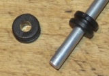
Note: This does include an SBC of 0 mm

Table 2-2: 2 m section, 6.00 mm elements through a 15 x 15 mm boom,
formast mount with 280 mm offset on rear boom end:
"Ready to saw and drill" data for mounting elements through boom with BC according SM5BSZ's BC.exe:
|
This table is only valid for: Boom shape: square Boom dim: 15 x 15 mm Wall thickn.: 1.0 mm Holes in boom: 8.0 mm Offset rear: 280 mm Offset front: 30 mm |
|
Note: This does include an SBC of 0 mm

Table 2-3: 2 m section, 6.35 mm elements through a 5/8 inch boom,
formast mount with 280 mm offset on rear boom end:
"Ready to saw and drill" data for mounting elements through boom with BC according SM5BSZ's BC.exe:
|
This table is only valid for: Boom shape: square Boom dim: 5/8 x 5/8 inch Wall thickn.: 1/6 inch = 1.6 mm Holes in boom: 8.0 mm Offset rear: 280 mm Offset front: 30 mm |
|
Note: This does include an SBC of 0 mm
Table 70-3: 70 cm section, 6.35 mm elements through a 5/8 inch boom,
formast mount with 280 mm offset on rear boom end:
"Ready to saw and drill" data for mounting elements through boom with BC according SM5BSZ's BC.exe:
|
This table is only valid for: Boom shape: square Boom dim: 5/8 x 5/8 inch Wall thickn.: 1/6 inch = 1.6 mm Holes in boom: 8.0 mm Offset rear: 280 mm Offset front: 30 mm |
|
Note: This does include an SBC of 1.74 mm plus a correction for the insulators (v-factor!) of 0.7 mm = 2.44 mm
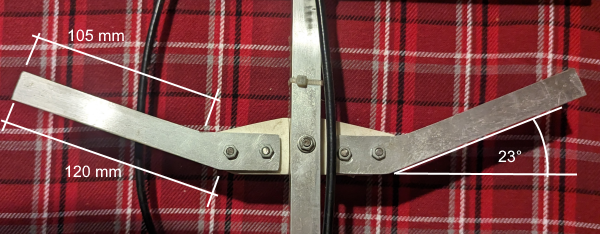
Sketch of Bent Dipole for 70 cm

M0ABA: Width of "blade edge near D1 is 120 mm and inside edge is 105 mm and sweep angle is 23 deg."
Building Details
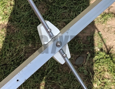
YBN 3+7 SAT - Detail: M0ABA constructed 2m dipole bracket
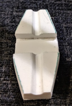
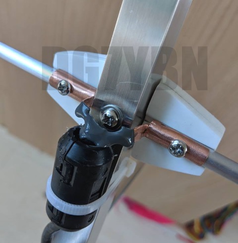
YBN 3+7 SAT - Detail: M0ABA constructed 70 cm dipole bracket. Note the rotatable arms for transport and trim
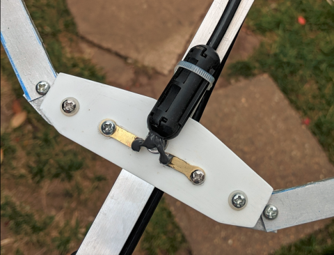
Images on courtesy of M0ABA, tnx Thomas!
Link to MX0CNS facebook for more photos and reports
Pattern and VSWR Plots
Current distribution Elevation and Azimuth plot at 145.8 MHz
VSWR plots - simulated 2 m
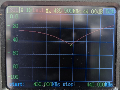
Return Loss plot - simulated 2 m
Elevation and Azimuth plot at 435.0 MHz
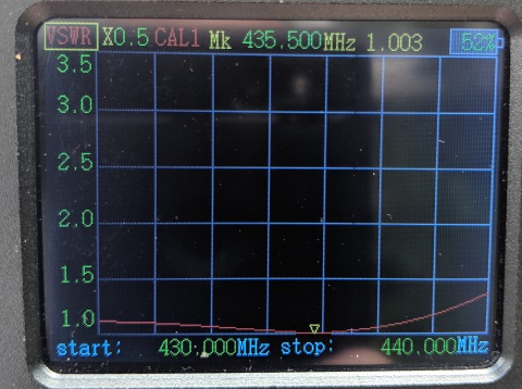
VSWR plots - simulated 70 cm
Return Loss plot - simulated 2 m
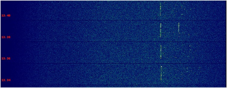
Moon Bouncing
Though 432.1 MHz is a little off band for the SAT 435.5 MHz Yagi it shows its wideband nature
in an easy EME QSO ... on 2019-05-11 M0ABA / MX0CNS made a 70 cm EME contact with DL7APV, first using 60 w out,
later reducing output to 10 w.
10 w QSO screenshots: MX0CNS was B-26 dB at DL7APV
73, Hartmut, DG7YBN