-
• Main Page
- • Home
• Antennas - • 144 MHz
- Bent dipole GTV
144 MHz YagisGTV 2-7w: 2.7 m wide band width version of the low impedance, yet 50 ohms direct feed Low Noise Yagi with bent DE introduced in Dubus 1/2013
Elevation Plot

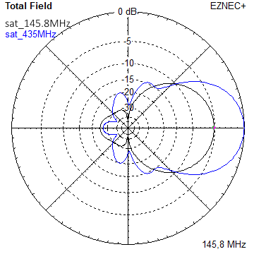
- YBN 3+7 SATA Satellite Yagi with 3 ele. for 145 MHz + 7 ele. for 435 MHz for handheld use
Elevation Plots
- YBN 2-2wA 50 ohms direct feed 2 ele. Yagi with high potential as broad beam Contest Stack.
See yourself and compare to DJ9HO Double Quads and 7ZB Oblongs. Full details on 2 and 4 Yagi stacks are given
3D Pattern of 4 x Stack

- YBN 2-5m (5-8)1.6 m high F/R, good willing 50 ohms direct feed Yagi as introduced with bent DE short version of the 5-8 in Dubus 4/2012
Elevation Plot

- YBN 2-6m 1.9 m long, good willing 50 ohms direct feed Yagi, related to the 5-8 project (same positions refl, dipole, D1, D2 ... same size folded dipole)
Elevation Plot
- YBN 2-7m 2.8 m high F/R, good willing 50 ohms direct feed Yagi, related to the 5-8 project (same positions refl, dipole, D1, D2 ... same size folded dipole)
Elevation Plot
- YBN 2-7mz 28 Ω2.8 m high F/R, good willing 28 ohms direct feed Yagi
Elevation Plot

- YBN 2-8m (5-8)3.6 m nice G/T, good willing 50 ohms direct feed Yagi as introduced with bent DE expanded version of the 5-8 in Dubus 4/2012
Actually it seems to be so good that DK7ZB decided to use it as draft for the 8 ele. OWM he just published.
Elevation Plot
- YBN 2-8mz 28 Ω3.6 m 25/28 ohms version of the YBN 2-8m
The stacked 25 ohms Yagi can easily be phased with 50 ohms coax cables
Elevation Plot
- YBN 2-9mz 28 Ω4.3 m high F/R, high G/Ta 28 ohms Yagi
Elevation Plot

- YBN 2-9m4.5 m moderate band width, low Antenna Temperature, good willing 50 ohms direct feed Yagi - a straigh DE version twin to the GTV 2-9m
Elevation Plot
- YBN 2-10w (5-8)5 m wide band, good willing 50 ohms direct feed Yagi as introduced with straight DE expanded version of the 5-8 in Dubus 4/2012
Elevation Plot
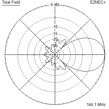
- YBN 2-10wz 12.5Ω5.1 m - 144.0 to 144.8 MHz wide band 12 ohms OWL-style Low Noise Yagi with straight DE and very low back lobes only
Elevation Plot
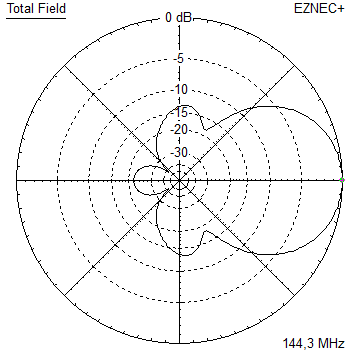
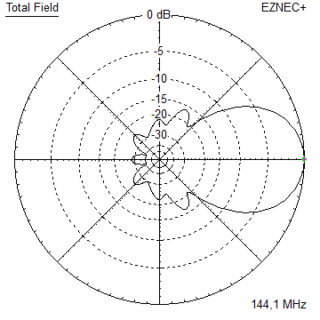
- YBN 2-12wz 12.5Ω6.8 m wide band 12 ohms OWL-style Low Noise Yagi with straight DE and very low back lobes only
Azimuth Plot:
- Bent dipole GTV
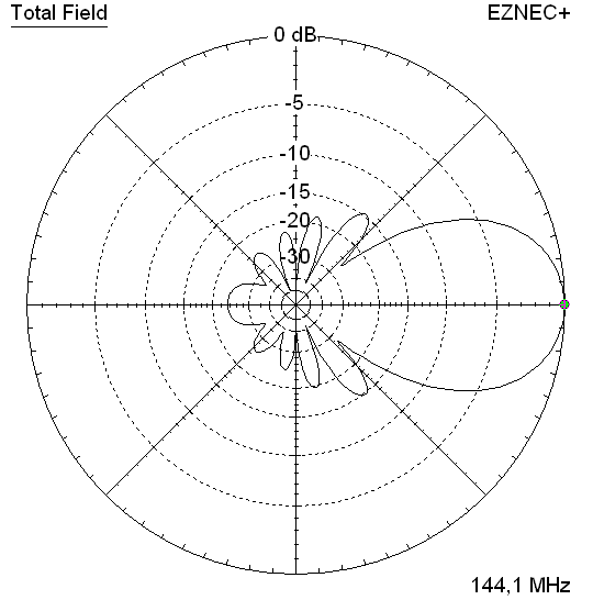
YBN 2-10wz wide band 12.5 ohms Yagi with straight dipole
144.0 to 144.8 MHz Wideband Antenna Version (OWA style)
This Yagi is balanced between gain and low back lobes. It may serve as an all-round antenna for Tropo and Contest
or make a nice EME bay due to its respectable G/T number. The straight DE may be matched to 50 ohms at feed point with an
improved DK7ZB style 2 x 50 ohms quarter wave line (see end of page).
This Yagi was derived by modifying the GTV2-10LT to 12.5 ohms while adding a little band width.
Current distribution


Antenna Temp. incl. losses: T_total = 227.5 K, G/T = -9.17 dB for the single Yagi
Performance Data
Gain vs. isotr. Rad.  14.4 dBi
Gain vs. Dipole       12.3 dBD
-3 dB E-plane         36.4 deg.
-3 dB H-plane         40.2 deg.
F/B                  -25.0 dB
F/R                  -25.0 dB
Impedance             12.5 ohms
Mechan. Length        5074 mm
Electr. Length        2.44 λ

Stacking Dist. h-pol.    DL6WU     max. G/T
top-to-bottom           3.03 m      3.45 m
side-by-side            3.35 m      3.75 m

For building ...
SegmentationBC = +2.3 mm = (144.8 MHz - 144.4 MHz) * 5.85 mm/MHz
Geometry
8 mm Elements:


Building Plan

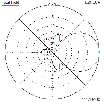
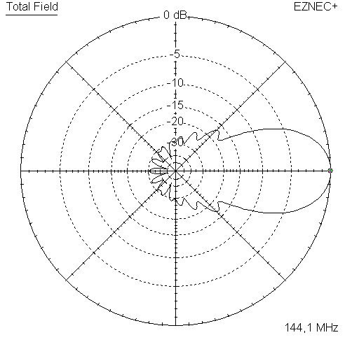
Pattern and VSWR Plots
Elevation and Azimuth plot at 144.1 MHz

SWR and Return Loss plots - simulated with 4nec2


Folded Dipole 12.5 to 50 ohms Version

The Folded Dipole is made from 10 mm aluminuim tube: 959 mm outside / outside, with a bending diameter of 54 mm inside the bends.

It would be practicable to buy a larger one, cut it left/right side,
insert pieces of 8 x 1 mm tubes and use tiny hose clamps or screws to fasten the pieces when adjusted to length.
As an alternative one could use just the bent ends and push these into 12.0 x 1 mm tubes as arms of the DE.
BUT: making a Folded DE is not that difficult, here is the link to G3SEK's good website on making one: www.ifwtech.co.uk/g3sek/diy-yagi/dipoles.htm
SWR and Return Loss Plot
This is modeled with typical offset to element plain caused by on-boom mounting of elements. D1 is 1 mm longer here!

Downloads
EZNEC file of this Yagi
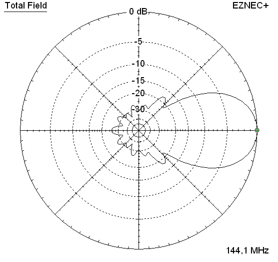
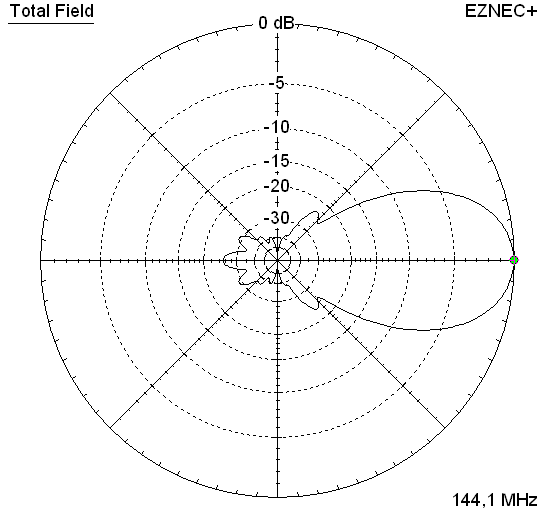
Stacking

Stacking Dist.    DL6WU Formula    max. G/T
H-plane               3.03 m        3.45 m
E-plane               3.35 m        3.75 m
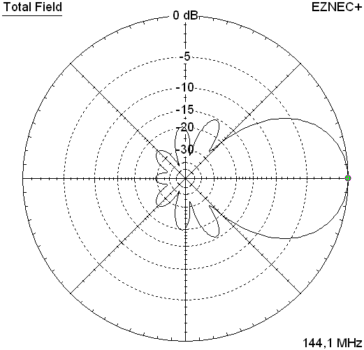
Elevation and azimuth plot and data of 4 Yagi bay using DL6WU stacking distances


Gain vs. isotr. Rad.  20.31 dBi
Gain vs. Dipole       18.16 dBD
-3 dB H-plane         16.3 deg.
-3 dB E-plane         18.2 deg.
F/B                  -26.4 dB
F/R                  -26.4 dB
T_ant                228.6 K*
G/T                  -3.29 dB*
Theoretical numbers, no phasing line losses
nor imperfections caused by H-frame included
*) T_sky = 200 K, T_earth = 1000 K as in VE7BQH G/T table
Data of 4 Yagi bay using max. G/T stacking distances
Gain vs. isotr. Rad.  20.48 dBi
Gain vs. Dipole       18.33 dBD
T_ant                236.8 K*
G/T                  -3.26 dB*
Theoretical numbers, no phasing line losses
nor imperfections caused by H-frame included
*) T_sky = 200 K, T_earth = 1000 K as in VE7BQH G/T table
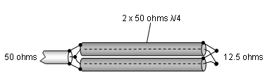
Matching 12.5 to 50 ohms
Coax line transformer principle and applied concept = the ferrite improved DK7ZB - Match

 Attenzione!
Take care when lengthening the cables, measure the right length instead of refering to given v-factors only.
Attenzione!
Take care when lengthening the cables, measure the right length instead of refering to given v-factors only.A good choice may be the diam. 5 mm PTFE coax RG-142 B/U: real resonate length (144.1 Mhz) shield-shield is around 345 mm
 Find more information on my Phasing & Matching Lines page
 Detailed Building Plans
Scaled Drawing of Boom Parts 1, 2, 3

Scaled Drawing of on half of the symmetrical Boom Strut

Find more information on bending the strut on the Yagi Booms and Struts page73, Hartmut, DG7YBN