-
• Main Page
- • Home • Building
-
- Boom CorrectionIntro to Boom Correction and complete Collection of Factors

• DL6WU / G3SEK formulas and charts in detail
• DJ9BV insulated through boom
• I0JXX insulated through boom
• K1FO insulated through boom
• VE7BQH Cushcraft & Cudee on Boom
• DG7YBN semi-insulated on Boom
• Intro to SM5BSZ's BC.exe
• Segmentation Issues and more ... - Symm. & BalunsSymmetrising Devices from Sleeve Balun, F9FT Tube, EMI, G0KSC, Pawsey, 50 ohms Quarter Wave Line to 12.5 and 28 ohms DK7ZB Match ... plus Test Equipment - the RF Current Meter
- Howto - Bent DEHow to bent a GTV Yagi DE with a simple selfmade tool:
Bending aluminium tubes by hand leads to buckles and brocken tubes. So I show what a simple selfmade tool looks like. You will need just a piece of wood, a few minutes and a jigsaw to produce one.
It will make the job much easier.
DIY - Bending Tool

- Building a YagiA collection of building hints - from DE-Box to bending Support Struts and mounting Elements. - Under Construction -
- Boom StrutsA collection of building hints - Planning and bending Support Struts and making bending tools. - Under Construction -
- Scaling Yagi ElementsHow to scale complet Yagis in Frequency and Element diameters from one dimension to another by hand
• Stacking
- Boom Correction
- Phasing & Matching LinesHow to measure coax stub lines, produce coaxial impedance transformation lines, Baluns and how to stack and match with coax lines
- Coax & Splitter Online CalculatorCoaxial Line Impedances Online Calculator, Intro to Power Splitters and Power Splitter Dimensioning Online Calculator


Coax Cable Transformers
Real Coax Cables
Coaxial Transformers are of relatively narrow -3 dB bandwidth.
Broadband Transformers
For matching TV or LTE Antennas a broadband transformer that covers
several 10 MHz or even the whole UHF TV band is to be preferred.
Half Wave Balun for Folded Dipoles
Odd multiples of λ/4
Feeding stacked Antennas with Coax
Connecting Array Dipoles in Phase
Preface: How to trim coax to length & why v-factor is depending on frequency
 Attenzione!
It is understood that a length of coax cable needs to be shortened using its velocity factor
if we want to cut a resonate length. A waves speed in a medium is described as

According IEC 60250 the dielectrical constant εr of (natural) PTFE is 2.1, measured at 1 MHz equalling v = 0.690 = 69%. However Radio Amateurs mostly use v = 0.7... 0.71 so that the calculated length of a 144 MHz Quarter Wave Line is around 369 mm.
But have you ever measured the resonance frequency what you have cut? At VHF and above you will probably be surprised to find your stub being some 5...10% too low in resonance frequency. This is due to εr and v-factor being specified at a much lower frequency and plastics dielectrical properties are frequency depending to a certian extend.
The full story is that plastics hold a so called Dynamic Dielectrical Constant:
    M. Bonnet, Kunststoffe in der Ingenieuranwendung, Vieweg + Teubner, Wiesbaden 2009, pg. 73
    Chapter 1.7.1.3 Dynamic Dielectrical Constant and Dielectrical Loss

    My translation from original German text:

    'In an alternating electrical field the electrical dipoles [of the plastic]
    are forced to oscillate with frequency ν of the alternating field. Molecules
    with orientation polarisation are hereby constantly forced to alter their alignment
    in the volume. This leads to relaxation damping.'
It is said relaxation damping that degrades the dielectrical constant with increasing frequency, which lowers the wave speed in the plastic. That makes our velocity factor drop - and so needs our coax stubs length at VHF and above. Eventually measuring and tuning in the exact length of your VHF/UHF coax balun or quarter wave lines is a must if it shall be precise. Not to mention the influence of all connecting open coax ends.
 How to measure a coax lines resonance frequency
Any quarter lambda of coax line acts as a resonate circuit. Any odd multiple length does too. A λ/2 balun line can be measured as quarter lambda at the resulting frequency. On VHF/UHF the true resonate length will be some 5 to 7% shorter than calculated.

Using the Dipmeter
Join one sides split ends, take a dipmeter and go ... . Most dipmeters frequency readings are not as accurate as we would like to have it. So I run my station RX on 144.200 MHz and listen for the "dip" to come by. You might add a mark to your dipmeters scale then.

Using a Network Analyser
If your Network Analyser can perform transmission mode you have an quite accurate instrument at hand. Basically the S21 network parameter is same as transmission mode.
Principle
Inductive coupling


If you are a newbie using analysers you may read my 'Intro to Analysers' - here
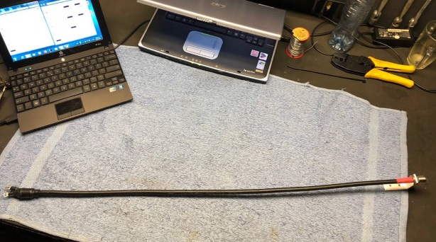
A piece of H2010 trimmed to resonate at 144.1 and harmonics (with OBZOR / Planar TR1300 VNA)

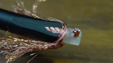
And here is the piece of coax the above plot belongs to ... it is the very new H2010 coax cable

That line is ment to perform in the prototype of my 432 MHz GTV 70-19m.
As the H2010 is very low loss (8.68 dB per 100 m on 432 MHz), UV resistent, has a flexible core, water rejecting PE foam dielectricum, and handles almost 1 kW on 432 MHz I think it is the right choice for a 70 cm high grade Yagi.
A test length was kindly provided by Kabel Kusch - TNX!
This length is a 1/4 λ on 144 MHz and 3 x 1/4 λ on 432 MHz. Just as the above VNA plot shows. Using odd multiples on 3rd harmonic frequency does not change anything since we can look upon this length as a single Quarter Wave Line followed by a halfwave length - with does not change anything on the impedance - apart from the little loss it brings.
So that this line works in a 144 MHz as well as in a 432 MHz Yagi as a symmetrising 50 to 50 ohm member ... the better so when a ferrite core is added close to the driven element feed point.

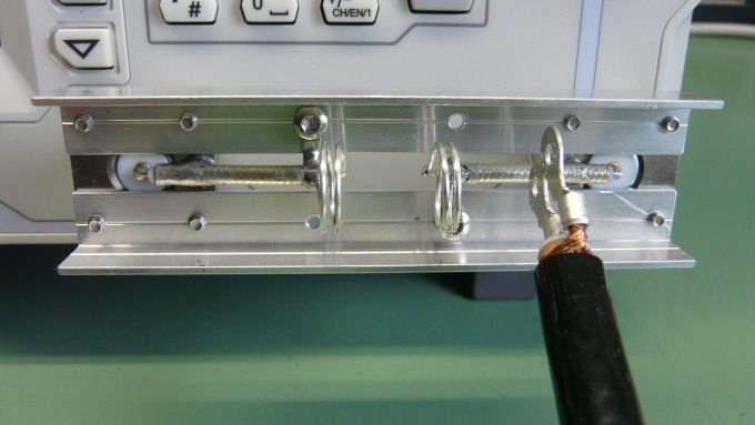
In transmission mode the analyser will show the transmisson properties of whatever is fitted between the DUT and DET ports. If we use two coax lines with coils at the ends and place the short circuited end of the to be measured stub between these coupling coils we find the transmisson path being disturbed by the stub where it is resonate. See the little peak in image below? That is our frequency reading. Loose coupling, just enough to notice a tiny wobble is best since it will least influence the resonance of the stub.
From theory to real world:
Photos on courtesy of Erwin, DK5EW who tested this himself ... (inductive coupling, VNA side coax shortened, far end open)


These measurement coaxes might be a little short for use on 432 MHz. Not to create build in resonances or quarterwave lines in there!
DK5EW measures 144.40 MHz for 342 mm of RG-142 PFTE coax; I found 345 mm for 144.20 MHz for same RG-142:

A coupling plate made out of a defective coax relay at DG7YBN (capacitive coupling); VNA side end open, other shortened

The commonly used v-factor (for 1 MHz) has it with 369 mm - which leaves you with a quarter wave coax perfectly cut ... for around 133 MHz instead. If you install that likewise as 2 x 75 ohms into a Yagi it does not take rocket science to find out why you might think you do not need a BC on that build. For any conventional Yagi-Uda it is the excess length of that matching coax that will add to the DE and make it appear longer and compensate for the falling short elements. Which works out for the respondig frequency but surely not for the pattern.
Inductive Coupling Bridge to VNA by DL2VL (tnx Jörg)

INTSAT 220 Elite

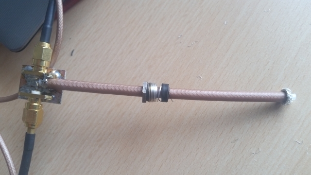
Measuring a 1/4 λ line as a stub, per by PA2CV, Alex:
Alex produced a measurement bridge from two lengths of coax with SMA connectors, calibrated the bridge without the stub, soldered the Quarterwave line to the SMA connection and plotted the Return Loss (S11), see below. A fair methode that overcomes the challenges of the tricky capacitive or inductive coupling the transmission mode methode holds.


Measurement with such a brigde by DG7YBN, LiteVNA 62 and nanoVNA-App 1.1.209:
Coax is RG-58/U PE (Belden 9201), length of braid: 319 mm;
Measuring Mode: Fre. Log. Mag. S21 (dB):

Looking at 3rd, 5th and 7th harmonic we find either the v-factor running even further a way from the 0.66 given by the manufacturer at probably 1 MHz or the 5 to 7 mm split ends on both sides are less and less adequate at 700 or 1000 Mhz.
Measuring a 1/4 λ line as a stub, performed by PA2CV, Alex:
432 MHz 1/4 λ line from RG-142
Lambda/4 - Common Mode Choke / Sleeve Balun for GTV 70-25, performed by DF7KB, Wolf:
Wolf has connected 2 SMA bushings with a 50 ohms stripline:
"The frequency response is almost flat (to above 1500 MHz). I connected the just produced sleeve balun. Whcih results in a measurement depth of 30 - 40 dB."
Fig. 1 shows four coaxial Lambda / 4 sleeve baluns. Their geometry is:
Core Rod: Diameter = 5 mm; Length = 141,5 mm
Outer Tube: Diameter 14 / 12 mm; Length = 142 mm
The core rod is centered by a PFTE ring (thickness 2 mm). The pin of the N socket
centers on the other side.

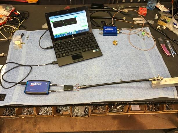
"Fig. 1 also shows the "aluminium provisional boom" and the coupling with measurement coaxes to the VNA
This coupling consists of a 50 ohms strpline which ends into two SMA bushings.
The frequency slope of this probe is almost linear up to 1500 MHz.
The core of the sleeve balun is soldered to the stripline, the outer conductor is
connected to the gnd of the stripline."
Fig. 2 shows the test setup. Provisional boom and ferrite core do shift resonance of the sleeve balun up to a total of 500 kHz and thus should be incorporated when tuning.
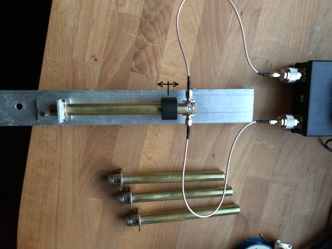


• Shift of resonance spot with boom: approx. 100 kHz
• Shift of resonance spot with ferrite: approx. 200 kHz
Below: coupling inductances for inductive coupling of stubs for plotting in Transmission Mode


Setup, text und photos kindly provided by Wolf, DF7KB
Measuring a 1/4 λ line cross checking results inductive vs. stripline bridge coupling by John, ZS6JON
John wanted to cross check between both methods
• the inductive coupling of a stub als a 1/4 wl ciruit in transmission mode
• the stripline bridge as real stub in a transmission line.
First the classical 1/4 wl ciruit in transmission mode phase change plot:


Note that for very accurate measurements details as
• position of the ferrite core
• a substitue boom and height of coax line above that
will make the difference on the few 100 kHz
Measuring a 1/4 λ line for the 4 m band by John, ZS6JON

• Find sample VNA plots of a full Yagi with right and wrong lengths of matching coax on Symmetrising Website
Coax Transformers
How to determine the needed Z for a wanted Quarter Wave Lines tranformation ratio

Some applied examples
1.  From 50 ohms feedline to 12.5 ohms Yagi with straight split DE?
    Z = sqrt ( 50 ohms x 12.5 ohms) = 25 ohms
    This we can produce by using two 50 ohms Quarter Wave Lines in parallel

2.  From 50 ohms feedline to 28 ohms Yagi with straight split DE?
    Z = sqrt ( 50 ohms  x  28 ohms) = 37.4 ohms
    This we nearly can produce by using two 75 ohms Quarter Wave Lines in parallel

3.  And finally the trivial case:
    From 50 ohms feedline to 50 ohms Yagi with straight split DE?
    Z = sqrt ( 50 ohms x 50 ohms) = 50 ohms
How to transform from 50 ohms to 12.5 ohms using parallel Quarter Wave Lines

How to transform from 50 ohms to 28 ohms using parallel Quarter Wave Lines (aka DK7ZB - Match)

How to transform from 50 ohms to 200 ohms using parallel Quarter Wave Lines // corrected 2014-09-23, tnx DH1LM,
who showed me that the old sketch was wrong. Hopefully this one does ...
How to transform from 50 ohms to 75 ohms using parallel Twelfth Wave Lines

How produce Ferrite RF Transformers for various impedances transformation ratios
• Ferrite Transformer
Image shows a 1:1 transformer as blue and black wires windings
ratio is 1:1. This one is for Shortwave use. For VHF / UHF dimensions must be much smaller.

Example: Za = 50 ohms, Zb = 200 ohms ...
Na = 6 wdg; Nb = 12 wdg => Na/Nb = 6/12 = 0.5
Transformation ratio = (Na/Nb)xy2 = 0.25 = 1/4 or 1:4
200 ohms x 0.25 = 50 ohms
• Balun Transformer
![]()
The transformation ratio is same as described above, but now the 50 ohms side is unbalanced (coax feed)
while the 200 ohms side is balanced or symmetrical.
An often seeked for transformation ratio might be 50 to 75 ohms.
This could be acheived using 6 and 9 wdg. respectively 6 + 3 wdg on the Balun Transformer.
• What about the size of the ferrite then?
For any receiving purpose it may be very small. Same to the wire diameters. A tiny ferrite bead equipped with 0.12 mm or so enameled copper wire will do for most purposes. For handling transmitting power or limits issuing intermodulation there is one rule: The ferrite must not saturate. Big is beautiful and size does matter here. Unlike with applications for short wave where ferrite baluns in transmitting antennas are widely used we have only few data and less working ferrite materials when we talk VHF / UHF applications. A rule of thumbs is .. it must not heat up much, it shall not get hot of very warm during transmitting. Having large size ferrites and wires wrapped around is in contradiction to the need for shortest wires on VHF / UHF. That is why we find receiving purpose small ferrite bead based transformers often, but power handling transmitting transformer very seldom here.
Real dimensions: using very small double hole ferrites in a 144 MHz RX frontend
![]()
![]()
However here is a little table holding some suitable types, makes and sizes for VHF / UHF transmitting purpose ferrite transformers
Size Amidon T37 or T50, inner diam. = 5.21 / 7.70 mm fit RG58 and RG142 B/U Teflon coax.
Size Amidon T80, inner diam. = 12.60 mm fits RG213 coax, Aircell ...
Code T50-0 (color code: brown) covers 50-300 MHz
Material 43 is for blocking VHF/UHF frequencies
A good choice are the following cores:
FT 50 B-43 inner diam. 7.9 mm, outer diam 12.7 mm, length 12.7 mm (approx EUR 3 pp.)
FB-43-5621 inner diam. 6.4 mm, outer diam. 14.3 mm, length 28.6 mm
FB 43-1020 inner diam. 12.7 mm, outer diam. 25.4 mm, length 28.2 mm
A commerially made broad band Transformer to match 75 ohms feedline coax to a 300 ohms UHF TV antenna
PCB with inductances.
Designing something like this is rather complex and usually done using an 'EM' software like Sonnet EM, FEKO, ADS ... . So I just show an example. For those who want to dig themselfs into the topic: There are free, limited in size of analysed object versions like 'Sonnet EM Lite' available.
![]()
For an etched on PCB solution for 70 cm Amateur Radio Band that does 50 to 28 ohms see here
How to transform from 50 ohms to 200 ohms to feed a Folded Dipole as Driven Element

What to avoid feeding a Folded DE

Tape it to the boom right from the connector or box on, or leave it hanging for much longer than λ/4 x v-factor.
Note: Any odd multiple of λ/4 such as 5/4 λ or 7/4 λ will transform exactly as the sole λ/4 line. Why so?
Because a half wave line does not change anything, apart from losses. Any odd number of λ/4 can be seen as a number of half wave lines plus a single λ/4 wave line.

Same would apply to 144 MHz splitters to use on 432 Mhz and so forth. Any tripple frequency ... just mind connecting bushings pins inductances or coax pigtails that have more impact on that tripple frequency.
Feeding stacked Antennas with Coax
How to feed two 25 ohm Antennas from 50 ohm coax

How to feed two 50 ohm Antennas from 50 ohm coax
• Simple Way:
| Attenzione! |
Building this 75 ohms coaxial cable splitters with 50 ohms T-connectors will not satisfy. A small length of 50 ohms instead of 75 ohms just before the sum point is an impedance discontinuity serious enough to prevent the VSWR from being better than appox. 1:1.2 |
• Improved Way with short tranformation line:

|
A small length of 1/25wl of 75 ohms coax before the sum point yields a better adaption between 50 ohms feed and the two legs. Note: the same small length of 75 ohms coax as added in front must be added to each leg. |
VE2ULU advanced 2 way splitter with tuning stubs at the bushings (220 MHz)
In Dubus issue 3/2020 you find the full description of this 2 way splitter:
With a simple 2 leggesd coax network we can only expect a Return Loss (S11) around -16 ... -20 dB.
With an additional length of 1/25wl of 75 ohms coax before the sum point and additioanl trimming wires
which compensate the loads by the open bushing pins Return Loss can be dipped below -60 dB easily.
Mind that winding up the coax to fit a box will effect the electrical length of the legs.
Usually they need shortening when wound into loops.


Careful praparation of a coax cable leg ...


Description and Images if not stated otherwise: Luc Laplante, VE2ULU
Source: Luc Laplante, VE2ULU, Hartmut Klüver, DG7YBN: Coax Cable Two Way Dividers with improved Performance, Dubus 3/2020
How to feed four 50 ohm Antennas from 50 ohm coax
How to feed four 50 ohm Antennas in typical H-configuration from 50 ohm coax in style

How to get four Folded Dipoles fed in phase

• All shields are to be connected on same side
• All Folded Dipoles are facing upwards
... which in typical H-frame 4 bay configuration involves turning the struts of the lower pair upside down while elements and Dipole stay as on the upper pair. Or simply put: all dipole boxes or Matches face down.
How to get four Straight Split Dipoles fed in phase
• All shields are to be connected on same side
How to get a vertical 4 Yagi stack fed in phase

It is understood that all feeding coaxes (1,2,3,4) must be of similar length and impedances must be transformed as shown above or using a Power Splitter
Specificly:
Using similar lengths for all four feeding coaxes needs somehow winding up # 2 and 3. We find a remedy here using a length of minus full 360 degr. for the inner coaxes # 2, 3. As 360 degr. or even multiples of that do not change anything according feeding phase. With a lag of n x 360 degr. we are just at the same point on the sinus we find on the outer Yagis. Which in practise means we are feeding all dipoles in phase.
An example: 360 degr. is just 1.0 wavelength, multiplied with real velocity factor of coax to be used at designated frequency. Likewise v = 0.82 of some foam insulated coax on 144.1 MHz (2.080 m) makes 360 degr. of runtime on coax be equivalent to a length of 1.706 m Simply put: coaxes # 2, 3 can be 1.706 m shorter than the coaxes # 1, 4 feeding the outer dipoles.
• All shields are to be connected on same side
73, Hartmut, DG7YBN