|
....... |
How to link from your website to the "app"
The "app" as a link will appear where you have placed it on your site.
Clicking it will make your website contact my webserver and open the "app" just similar to doing that from this site.
But please keep in mind that Javascript must be activated on the client side for this. Every client i.e. internet user
is self responsible for appropriate browser security settings and up to date anti virus checks etc. on his/her PC.
No guarantee is given, whatsoever, use these lines at your own risk
And here is the set of formulas for computing velocity factor and round and square shields coaxial lines Z
Wherein Er is the dielectrical property or Permittivity of the dielectricums material from which we calculate the
actual velocity factor. Any Er > 1 will shorten the coaxial line since it decreases the waves velocity in relation
to speed of light; Log10 means to base of 10; D is the shields inner Ø or dimension; d is round cores outer Ø.
Comments & Hints
• Square shield factor: We find hints in literature that the factor of 1.08 expanding the round coax Z formula to
square shield is not on spot or limited to Z > 20 ohms and such (see http://oz2oe.dk/radio/combiner/combiner.html).
If in doubt I advise a cross check with the professionals tool "AppCad", see below.
• Other shapes: Need to determine any other HF line geometrie's Z like stripline etc.?
Go to http://www.hp.woodshot.com/ ... and download Agilent Technologies "AppCad" freeware
• Line length correction due to Connector Inductances: What may be much more inflicting the Return Loss or actual
resonace dips frequency of a real splitter build are the introduced additional inductances of the sum of connector pins.
|

|
Some numbers:
According DL7AFB a 3 mm length of open coax (RG213?) core equals 2nH
already (see http://www.mydarc.de/dl7afb/projects/3antennas.htm). If we assume same
number per N-connector, we likewise find 5 x 2nH shortening the Quarter Wave line length
in a λ/4 - 4 antenna port splitter.
In coarse approximation a 432 MHz splitters QW line with two ports per antenna side
should be shortened by 0.017 wl or 11 mm. That implies extrapolated minus 2 mm
per port or connector on 144 MHz, 5.5 mm per port on 432 MHz and much more on
1296 MHz. For the long, 2 x λ/4 splitters numbers are to be doubled, except for the feed
line port, when applied on the whole line length. In order to escape from that for 1296 MHz
and up flat stripline couplers are a good alternative.
|
Find approximated corrected equivalent QW line length in Splitter Calculator below.
Of coarse the splitter line impedance i.e. ratio of diameter core to shield and picked dimensions of the pair
has an impact here; which is not enclosed in the equivalent QW line length calculation.

|
For correct transformation we need the splitters line to to of 0.25 wave lengths and needed
Z on that length. The equivalent QW line length will bring the complete splitter back to be of a
quarter of a wave length. But the actual splitters line with needed Z_trans will be too short to
produce best performance.
|

|
Staying with the standard way of building splitters from square tube aluminium and N-connector
bushings we have to bite one of these bullets. Knowing that the cause of all this inconvenience is the
inductances from the sum of connector pins we can think about how to connect with less inductance.
|

Power Splitters in Detail
Splitter Calculator
3, 4 and 6 way splitters with λ/4 lines
2, 4, 6 or 8 way splitters with 2 x λ/4 lines
Use splitters on 3rd harmonic bands
Testing and plotting splitters
2 way splitters for 50, 60 and 75 ohms feed lines

How to determine dimensions for a transforming Quarter Wave Line splitter in 3 steps ...
(1.) Find resulting impedance on the left (antenna) side.
When feeding two lines of Z_x1 and Z_x2 into ports x1 and x2 the resulting impedance may be calculated as shown
below

For a pair of identical impedance it is simply half the single impedance of course.
	port x1		port x2		   Za
	50 ohms		50 ohms 	25.0 ohms
	60 ohms		60 ohms 	30.0 ohms
	75 ohms		75 ohms 	37.5 ohms
(2.) How to determine Z for a Quarter Wave line transforming between Za and Zb

Using this formula for calculating Z for a transforming Quarter Wave line we find
	Za	    	Zb		Z coax line
	25.0 ohms	50 ohms 	35.36 ohms
	30.0 ohms	50 ohms 	38.73 ohms
	37.5 ohms	50 ohms 	43.30 ohms

	Za	    	Zb		Z coax line
	25.0 ohms	60 ohms 	38.73 ohms
	30.0 ohms	60 ohms 	42.43 ohms
	37.5 ohms	60 ohms 	47.43 ohms

	Za	    	Zb		Z coax line
	25.0 ohms	75 ohms 	43.30 ohms
	30.0 ohms	75 ohms 	47.43 ohms
	37.5 ohms	75 ohms 	53.03 ohms
(3.) When having determined the needed Z of the splitter line proceed finding matching diameter dimensions in the
calculator on top of page
... or calculate whatever Z is needed using the form below
Power Splitter Line Z Calculator:
How to use this calculator: The sketch below shows a transformation line with ports (a) and (b). It may represent the power
splitter. Port (a) is the connection end for 2, 3, 4 ,6 antennas and (b) is the point to connect with 50, 60 or 75 ohms feedline.

Go to middle field and chose a "Type of Splitter". Next enter frequency and single antennas Z at point
(a) - usually 50 ohms - and feedline Z at point (b) - usually 50 ohms too. Finally chose a core diameter for the transformation
line or power splitter - the calculator will compute square and round shield (outer tube) dimensions plus informal Z as sum of
connected impedances of antennas (Imp .Za) and Z of the transformation line i.e. splitter and finally an equivalent length for
the splitters core.
There are two factors that influence the actual length of the transformation line: (1) the basic inductivity of connector pins,
(2) a Shield to Core (D/d) equivalent length which weights the length of connector pins from outer to inner tube. Here you may
opt for a factor or "Ignore all" - which leads to computation of the 'pure' 1/4 λ length This correction is but an estimation, I
have enclosed chosing from 0 to 4 nH per pin. 1.0 nH as default seems reasonable for N-bushings but that depends on
connectors used of coarse.
|
|
For using this calculator Javascript must be activated
n ports on λ/4 = short splitter with n ports on single side
2 x n ports on 2 x λ/4 = long or "λ/2" splitter with n ports on either side
• Find core's length in "Equiv. QW length" textbox. Er = 1 (air) is estimated for all. For λ/2 double core length.
Select "D/d ->eqv.lgt" => "Ignore all" for result exclusive approximated port impedances.
• An average dim. N-connectors pin may be around 1.0 to 2.0 nH.
• use Select "D/d ->eqv.lgt" => ... x 0.5 to split imperfection between
length with right Z and resonance of whole splitter
to yield best splitter tube length ... unless you ar planning something special
Image: © Dr. Tanja Kurzenknabe
|
See plot of a build with inductance at ports correction applied, here 
Back up page Back to Splitters Menu

How good a Return Loss can my Power Splitter show in an optimistic case?
Everbody wants to build a nicely working Power Splitter. Down the page I show examples reaching down to Return Losses
of -38 to -47 dB. Which is equivalent to a VSWR of < 1.02 ... 1.01. What limits the quality of our splitter?
First we take a look at the omnipresent basic formula Z = R + j X

(1) In correct terminology what I use as Z in text and online calculators is just R alone.
In a simplified view
(2) The ratio of the tramsformation lines inner to outer diameters makes the R of that line
(3) The overall lenght with the sum of connecting bushings pins inductivities added makes the jX
Looking at the real part of Z, the R alone we find a limitation to the outcome of the splitters Return Loss
at perfect imaginary part of Z, the jX = 0! as follows

	   Z = R at jX = 0   Return Loss
		48.0 ohms    -33.8 dB
		49.0 ohms    -39.9 dB
		49.5 ohms    -45,5 dB
		49.8 ohms    -54.0 dB
		50.0 ohms     infinte
		50.2 ohms    -54.0 dB
		50.5 ohms    -46.1 dB
		51.0 ohms    -40.1 dB
		52.0 ohms    -34.2 dB
An example
If now your inner to outer tube ratio gives a Z = 47.2 ohms your splitter can not get any better than
producing a Return Loss of -30.8 dB or a VSWR of 1.06. And that is with ideal fitting of connection
bushings pins inductivities to lenght of the splitter tube.
The other component, the jX is more complex
Besides this little play of words here are some parameters at work. For instance the often
relatively unknown properties of the to be used connection bushings. And the overall Q of
the to be build splitter.
Use of Trimming Screws in Power Splitters
DUT is a 432 MHz power splitter which appeared to be short by several millimeters at 163 mm per side for the core tube.
In the following we found that the true length with the used tubes and bushings must be slightly in excess of 2 x 173 mm.
This splitter used 25 x 25 x 1.8 mm suare tube, 10 mm core, M5 trimming screws
Adding triming screws in variation of distance to the center feed we find
(a) the influence of the screws decreased by growing distance
(b) we are able to 'pull' the frequency response of a splitter by > 12 MHz easily (70 cm) or around 0.02 lambda.
(c) the applied trim goes one way, that is down in frequency
Interpreting the chart:
The splitters best frequency response was much too high without any trim screws applied.
The following chart shows best response and frequency it could be tuned down to depending on distance of trim screw to center.
Mind that we do not tune 'to frequency' alone but a bit on the Z of the coaxial circuit as well. So that approx. 60 mm seems a good
measure at least for this combination of core to outer tube ratio.
Peter, DJ4TC was willing to support this project. He did all the measurements I asked for.
Which deserves a big "Thank You" Peter!
Consequences:
As it is easy to trim a splitter down a few MHz (70 cm) it seems convenient to build with
with a very decent shortfall in core tube length and trim down a few MHz to designated operating frequency.
Common Errors and a Plastic Spacer Correction
(1) If you think it is wise to leave the core tube of the splitter a little longer, you will not be rewarded with best Return Loss.
Any excess length beyond the bushing pins will only mix with the jX of that 1/4 respectively 2 x 1/4 λ resonator the splitter actually is.

To make this clear: length means distance from pin to pin of the connection bushings.
(2) using plastic spacers is a good ides to increase stability and center the core tube

However, any plastic put over the core conductor tributes a velocity factor onto that stretch of conductor.
Just like in a common coax cable. At an estimated v ~ 0.6 will change the effective electrical length of a 10 mm
stretch of core covered in plastic to effectively 16.7 mm.
Using the common correction factors for half wave Yagi antenna elements of 5.85 mm (144 MHz), 1.02 mm (432 MHz) per
1 MHz leads to half that for a resonate 1/4 λ line as the splitter.
As an example 2 pieces of 10 mm spacers with a v-factor of 0.6 will extend the covered 20 mm x (1 / 0.6) by 13.0 mm.
With extends the cores electrical length by 20 + 13.3 = 33.3 mm. Which for a 144 MHz splitter means an decrease in
frequency by 2 x (13.3 mm / 5.85 mm/MHz) = 4.55 MHz.
Subtracting the excess length of 13 mm from the total length should compensate the effect caused by the 2 spacers.
Effective true compensation depends on having a true v-factor or permittivity of the to be used plastic
at the designated frequency at hand. Mind that plastics permittivity is frequency depending at VHF/UHF.
An EXPERIMENTAL Calculator
If this calculator works as it should, you fill in a length per 1/4 λ of Power Splitter core
taken from the above 'Power Splitter Line Z Calculator' with best adaption to port bushings inductivities
and add your spacers for a final correction of the core tubes length.
Take care, this is fully experimental but in theory should help to produce better results than
without and correction if you use plastic spacers. Any feedback on what this calculator delivers
is apprechiated!
Corrected algebraic sign of length influence 2016-03-02
Corrected influence of plastic on core following G6WQN's suggestion 2025-06-08, tnx Wilson!
3, 4 and 6 way splitters with λ/4 lines
The image is showing a 3 or 4 way splitter. Just imagine 3, 4 or 6 connectors mounted on left side.
How to calculate any cumulation of multiple Z's? Here is the generalised formula for not necessarily even single Z's.
It is Kirchhoff's law applied to impedances.

Index n is equivalent to number of ports per side. For a 4 way splitter n is 4.
For any number n of identical impedance it is simply the n-th part of the single impedance of course.
	Single Z's	Calc.	     Za
	2 x 50 ohms	50/2	 25.0 ohms
	4 x 50 ohms	50/4	 12.5 ohms
	3 x 75 ohms	75/3	 25.0 ohms
	...
From this we can derive that a 2 x 50 ohms to 50 ohms splitter may be used as 3 x 75 ohms to 50 ohms splitter too.
2, 4, 6 or 8 way splitters with 2 x λ/4 lines
The image is showing a 4 way splitter. Just imagine 1, 2, 3 or 4 connectors mounted either side.
These commonly are called λ/2 splitters. In my oppinon this name giving falsely suggests that we
would have a different transformation mechanism here.
A power splitter with 2 x λ/4 lines is a precise mirror image either side of what the half
numbers of antenna ports λ/4 splitter is. Just that the Z at feed point (x3) must be twice the number
since boths sides meeting results in half impedance.
Use same calculator as above. Match to Zb = 100 ohms at port x3 instead when feeding with 50 ohms coax
... any feed line Z must be multiplied by two.
Any splitters made from λ/4 lines can be used on 3rd harmonic bands
Every splitter using λ/4 or 2 x λ/4 lines may be used on tripple frequency too.
The transformating lines length is 3 x λ/4 then, which is equivalent to a single λ/4 line followed by
a λ/2 line, which does not change any properties.
A 144 MHz splitter will work fine on 432 MHz. Any 432 MHz splitter will give fine results on 1296 MHz. I have used
a quality 432 MHz λ/4 4 way splitter made by UKW-Berichte with success for feeding four Tonna 1296 MHz Yagis
in many contests.
Back up page Back to Splitters Menu
Testing and plotting Splitters
• A 70 cm band Splitter with Tuning Screws by Peter, DJ4TC
Dimensions: 25 x 25 x 1.8 mm aluminuim square tube, 10mm copper tube for core.
With an inner core diameter of 10.0 mm the inner of the outer square tube shall be 21.3 mm.
The used 25 x 25 mm with a wall thickness of 1.8 mm gives 21.4 mm inside. Fair enough ...
The inner round tubes length is 2 x 173 mm.
The outer square tubes length is 392 mm, which Peter reports to be not critical

The Splitter engages 4 galvanized trimming screws M5 at 70 mm from the center each.
Result: 173 mm per side is a little short,
giving -26 dB at 432 MHz and -28 dB on 443 MHz for best S11 exclusive trim screws.
But when trimmend the splitter easily reaches a Return Loss (S11 in dB) better- 40 dB.

• A 2m band Splitter with PTFE Tuning Screw by Wolf, DF7KB
The PTFE screw pushes the core tube slighty out of center, which
enables adaption of the impedance of the transformating path.
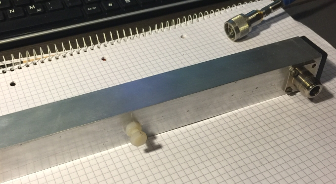
Side view: Here we see the PTFE cushion bearing rest for the core tube


Furthermore the second constructive detail:
A brass tube inserted into the copper core tube to adjust the frequency response
.. this resulting in a notable -60 dB at 145.5 MHz

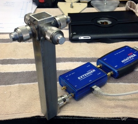
And the measurement equipment at DF7KB

A miniVNA PRO operated with Java SW vnaJ.3.1.9, calibrated with WiMo's set SMA 50 Ohm, SMA short circuit and
open ports. The coax for calibrating the 4 pole measurements is Suhner Sucoflex with SMA connectors.
"I have connected the 2-way power splitter with 2 x 10 dB precision attenuators followed by 2 x SMA 50 ohms terminations.
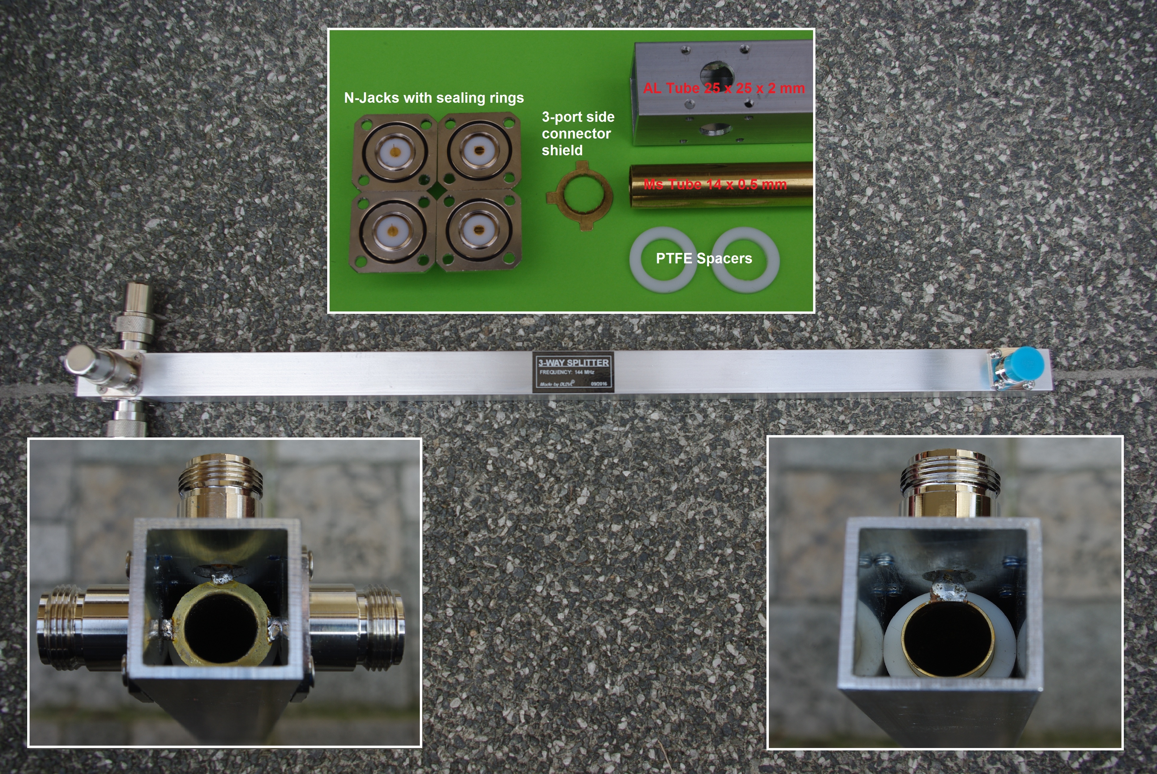
• A fine tuned 144 MHz 3-way λ/4 splitter made and tested by Jörg, DL2VL
Yet another remarkable produce by DL2VL. A way to yield same low Return Loss numbers as with the 'Tunable Splitters'
I show below and are subject of my article '2 m & 70 cm High Performance Power Splitters' in Dubus 2-2016.
Only that Jörg with his sense for fine mechanical solutions came up with a method of tuning length of the
splitters transformation line.
All photos,plot and build: on courtesy of DL2VL. Click the photo to enlarge.

The resulting Return Loss
And how he does it

First of all we notice the PFTE slices he uses to secure the conductor in the center of the outer square tube.
They do not only act as mechanical elements, they by their number also tune on the electrical length of the inner tube.
With 4 slices at the sum point and 1 at the split side he found the optimum for this pairing of tubes.
On top of that he machined an N-flange bushing that has a spring pin (!).
How to do that?
The pin is drilled hollow, then he places a tiny piece of rubber inside the opening and a sliding new pin follows.
Now what is that good for? ... with this bushing he can shift the position ie. alter the length of the transformation
line by very small amounts to do the final fine tuning.
Find details on the photos. Click to enlarge and view them full screen.
Hier die Daten des 3-Way 2m Splitters:

Außenleiter    25 x 25 x 2 mm        561,5 mm lang
Innenleiter    14,0  x 0,5 mm        511,5 mm lang
1-Port-Seite       4 x 2,5 mm = 10 mm PTFE
3-Port-Seite       1 x 2,5 mm PTFE
Impendanz 1-Port-Seite    (49,8 + j0,1) Ohm @ 144,2 MHz
Teilungsverlust            4,86 dB - 4,78 dB = 0,08 dB (S21= -0,08 dB)
Phasendifferenz 3-Port-Seite    <0,8°
(Messung mit Anritsu VNA)
And in English
Here the Data of the 3-Way 2m Splitter:

Outer Conductor    5 x 25 x 2 mm      length  561,5 mm
Core tube         14,0  x 0,5 mm      length  511,5 mm
1-Port-Side       4 x 2,5 mm = 10 mm PTFE
3-Port-Side       1 x 2,5 mm PTFE
Impendance 1-Port-Side    (49,8 ohms + j0,1) ohms @ 144,2 MHz
Splitting Loss             4,86 dB - 4,78 dB = 0,08 dB (S21= -0,08 dB)
Phase Difference 3-Port-Side    <0,8°
(Measured with an Anritsu VNA)

73!
Jörg, DL2VL
• An adjustable 432 MHz 4-way λ/2 splitter made and tested by John, ZS6JON
While the ideal inner diameter of the square outer tube would be 27.08 mm for the given cores diameter here a tube
with 28.6 mm is in use. Further with the tuning screws the frequency can be adjusted in a way that a slightly longer
tube can be used when the impedance of the splitter line is slightly higher than it should be.
For a 12.70 mm core the ideal outer square tubes inner diameter is 27.08 mm. With the available materials of 12.7 mm
core and 28.6 mm square tubes diameter the calculated Z is 53.2 ohms. Instead of the 50.0 ohms, that each
side of a 1/2 λ 4 way splitter should have. With those 53.2 ohms the splitter coax on its own would not
allow a Return Loss better than -32 dB.
The length of the core tube without tuning screws and right d/D ratio would be ~ 347 mm when ignoring all
corrections for bushing pin inductivities or d/D ratio correction. This tunable splitters core measures 362 mm,
that is an excess length o f at least 7.5 mm per 1/4 λ transformation way each side. It is that bit
longer because the capacitances introduced shorten it electrically.
The result is a 70 cm splitter with an unseen before fabulous input reflection of well beyond -50 dB on spot
on 432.1 MHz for EME operation without having to see a mechanical workshop to do diameters and lenghts of parts
to the 10th of a millimeter.

S11 (input reflection in dB) plotted with an Anritsu MS2000 series VNA
and calibrated measurement lines: Return Loss (432.1 MHz) = 54.9 dB

Same as Smith Chart: Z(432.1 MHz) = 50.3 + 0.3 ohms

And a drawing of that splitter, bushings are 'screw-in' type, tuning screws are 5M
Attenzione!
When building tunable splitters please make sure that
(1) the minimum distance between screws and coax core is sufficient for the used output power
(2) seal the screw from environmental influences like rain and air moisture
Aluminuim and stainless steel in some pairings are not very 'friendly' to one another as far as electrochemical
corrosion is concerned. Putting on clear coat paint on the outside seems a good idea.
• An adjustable 144 MHz 4-way λ/2 splitter made and tested by Stef, F4EZJ
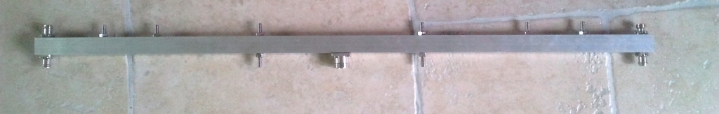
Stef built this splitter with a 7/16 DIN bushing at the feed point and 4 N bushings at the antenna ends.
The geometry is as follows:
Outer square tube 30 x 30 mm on the outside, 26 x 26 mm on the inside, length is 1047 mm
Inner core is a copper tube Ø 12 x 1 mm, length is 1019 mm
Tuning screws are M 8 and located at 140mm either side of the 7/16 bushing. Later he added more screws.
Which now help to trim down to close to -60 dB and in any case better -35 dB with whatever ~ 50 ohm loads / antennas connected.
External link to Stef's 'Onedrive' online album with many detailed photos

Stef uses the splitter for terrestrial work as contests and aimed for 144.30 MHz and here we are ...
Note:
Future builders might use M8 screws or maybe 2 screws in a row as for this build the space left between
screws and core tube is not much. More screws help to wider tuning abilities. See the photo above.
• A 144 MHz 4-way λ/2 splitter made and tested by Peter, DJ4TC
Calculated with the above online calculator adjusted 'nH/Port' = 1nH and 'D/d ->eqv.lgth' = 0.5 computing a length
of 509.5 mm. Making the core a 1019 mm (2 x 509.5mm) and the outer square profile a 1060 mm in length he plots a
Return Loss = -47 dB
and Z = 50.2 ohms at 144.1 MHz.
For this build he used a 25 x 25 mm outer dim., 1.5 mm wall thickness i.e. 22 x 22 mm inner size square tube
and a Ø 10 mm rod as core and quality N-bushings throughout

• A 432 MHz 4-way λ/4 splitter made and tested by John, ZS6JON
Note the 4 similar termination loads. It is essential to use good loads at each port to get true results ...

Freq. 432.14 MHz, RL = -44 dB, Z = 50.1 - 0.6 ohms, what more can we expect? Very good for EME
• A 144 MHz 4-way λ/4 splitter made and tested by John, ZS6JON

Note the 4 similar termination loads. It is essential to use good loads at each port to get true results ...
Freq. 144.161 MHz, RL = -38.1 ohms, Z = 51.0 - 0.8 ohms, very good for EME
For the above λ 1/4 splitters John used square aluminium tubes 25 x 25 mm with 1.6 mm wall thickness. That leaves
an inner height of 25 - (2 x 1.6) = 21.8 mm. Which suits 15 mm CU tubes as core. This diameters result in 27 ohms for the
transformation line. As the 25 x 25 mm tubes wall thickness is not very consistent it worked out better then that as we
can see from the plots he took. He uses my online calculator for determinating length and Z.
• A 144 MHz 4-way λ/2 splitter made and tested by John, ZS6JON


Freq. 144.161 MHz, RL = -37.5 ohms Z = 51.1 - 0.7 ohms, very good for EME
For this λ 1/2 splitter John used square aluminium tubes 25 x 25 mm with 1.6 mm wall thickness. That leaves in inner
height of 25 - (2 x 1.6) = 21.8 mm. Which suits 10 mm CU tubes as core. As he could not supply himself with that he found
9.7 mm tubes from the air-conditioning and refrigeration industry. This diameters result in 53 ohms for the transformation
line. As the 25 x 25 mm tubes wall thickness is not very consistent it worked out better then that as we can see from the
plots he took. He uses my online calculator for determinating length and Z.
Back up page Back to Splitters Menu
73, Hartmut, DG7YBN

|
|