-
• Main Page
- • Home • Building
-
- Boom CorrectionIntro to Boom Correction and complete Collection of Factors

• DL6WU / G3SEK formulas and charts in detail
• DJ9BV insulated through boom
• I0JXX insulated through boom
• K1FO insulated through boom
• VE7BQH Cushcraft & Cudee on Boom
• DG7YBN semi-insulated on Boom
• Intro to SM5BSZ's BC.exe
• Segmentation Issues and more ... - Symm. & BalunsSymmetrising Devices from Sleeve Balun, F9FT Tube, EMI, G0KSC, Pawsey, 50 ohms Quarter Wave Line to 12.5 and 28 ohms DK7ZB Match ... plus Test Equipment - the RF Current Meter
- Phasing & Matching LinesHow to measure coax stub lines, produce coaxial impedance transformation lines, Baluns and how to stack and match with coax lines
- Howto - Bent DEHow to bent a GTV Yagi DE with a simple selfmade tool:
Bending aluminium tubes by hand leads to buckles and brocken tubes. So I show what a simple selfmade tool looks like. You will need just a piece of wood, a few minutes and a jigsaw to produce one.
It will make the job much easier.
DIY - Bending Tool

- Building a YagiA collection of building hints - from DE-Box to bending Support Struts and mounting Elements. - Under Construction -
- Boom StrutsA collection of building hints - Planning and bending Support Struts and making bending tools. - Under Construction -
- Scaling Yagi ElementsHow to scale complet Yagis in Frequency and Element diameters from one dimension to another by hand
- Boom Correction
Bent Dipole
The Bent Dipole transforms from low impedance inside the Yagis structure to a higher impedance suiting the feedline coax.
Scrolling down you may think that its a lot of extra work - BUT - any other transformation like two parallel
Quarter Wave coaxes including water tightening all or employing a Folded DE means work too ... using a pipe bending tool makes things easy!
Blade Dipole for UHF
This dipole is made out of two pieces cut from an aluminium sheet with a jigsawNew rendered 3D CAD drawings: Click the image to enlarge

Why use such a flat dipole?
The 'Blade Dipole' cuts QRM like a hot knife through Butter ... is but an advertiser.
This dipole is applied on the GTV series Low Noise Yagis. Due to their high level of back and side lobe suppresson these antennas are capable of reducing pickup of QRM and QRN against non Low Noise designs by many dBs. The bent dipole is an integral part of such designs. It provides an internal match to a wanted feedpoint impedance of 50 ohms without using an additional transformation member.
When using very thin diameters like 4 mm for the dipole arms tuning becomes quite a twitchy business. For a real world UHF Yagi I also found a short bent rod of 10 x 1 mm aluminium to be difficult to produce. The broad flat outlines of the Blade Dipole ease the reactions of the antenna impdance. Same time I find it easier to reproduced a precise angle in cutting a shape from sheet metal then to bend a short rod.
Finally the make of a Blade Dipole as shown enables to mount the arms on precisely same height as elements mounted through the boom. Having zero offset between height of dipole arms and element plane means being as close a possible to simulated plattern and impedance parameters. This provides an excellent base for building Cross Yagis.
• Summarised
The matching of Blade Dipole and 4 ... 5 mm or 3/16 in elements mounted through boom with the advanced SM5BSZ Boom Correction (BC.exe) applied is an effective on. In my view it produces lightweight, very exact and inexpensive Long Yagis that are relatively easy to build and hard to beat when we compare net weight or wind load in ratio to Antenna G/T.
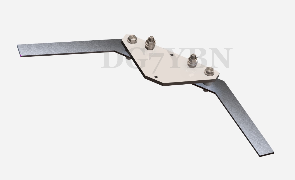
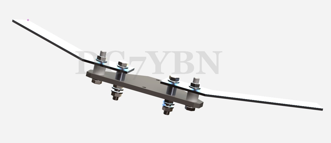
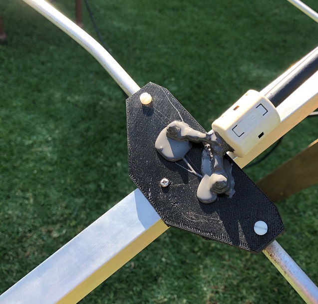
• Components of the Blade Dipole, exploded view
All the white is plastic: You could actually shape the base plate a bit like a rhombus, thinner towards the dipole arms. Materials: You can use a bit of PP, PE, PA, Acryl Glass or PFTE to make the mounting plate for the dipole halfs from. Non coloured plastic ie. 'natural' are to be prefered for RF properties, added UV stabilisers are to be preferred for long lasting builds. This will be a compromise issue. Size is not critical. Around 100 x 30 to 40 mm, t 4...6 mm
• Feeding Coax Cable
• Cross Sectional Drawing (Source Dubus 4/2014)
Note the screws for mounting the base plate to the boom is fastend in threads M3 cut into the boom tubes wall
Screws are M5 x 25 (boom 20x20 mm) for fastening the arms of the sheet metal dipole,
M3 for fastening plate to boom
• Base Plate: (a) = 46 mm. (b) = 84 mm, other plate dimensions are up to you but keep it relatively small please. This is for a 20 x 20 mm or 3/4 inch square boom and puts a distance of around 5 mm between boom and start of arms either side.
• Dipole arms: thickness of sheet metal is t = 2.0 mm. I think this is a good willing parameter, so that anything from t = 1.5 mm for a minium of mechanical stability to around 3 mm should work out without changing its flat dimensions.
• Layout of Blade Dipole arms
Every straight or folded dipole has to fit the very Yagi design in length. A Bent Dipole has to fit in length and bending angle. Even though more forgiving in dimensions the Blade Dipole does not make a general exception of that rule. A technical drawing in PDF format showing a layout of a Blade Dipole suitable for the 70 cm GTV 70-14 and GTV 70-19 you find in the download section of the 19 elem. Yagi
For a 403 MHz Radio Sonde tracking Yagi you find a Blade Dipole drawing in the download section of the GTV RS-19
For building other designs with a Blade Dipole dimensions have to be adapted. Mail me and I will help in this matter.
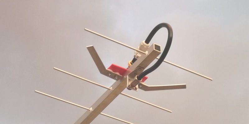
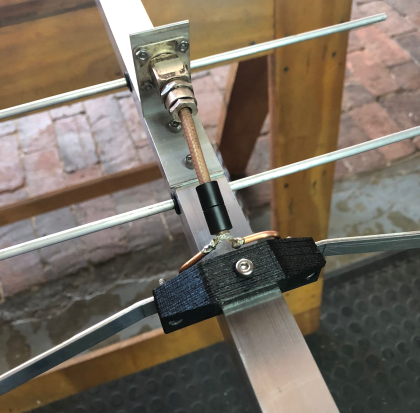
• Symmetrising Member - the coax you see on the inserted photos is a 3/4 λ (which is 3 x 1/4 λ) coax stub made from H2010 foam insulated low loss cable. Its length is 385 mm including the far side of the N-flange bushing it ends in. Find more details on getting the coax length right in section 'Phasing' of this website, here
Note the ferrite core placed close to the split point (photo on right).
This dipole is applied on the GTV series Low Noise Yagis. Due to their high level of back and side lobe suppresson these antennas are capable of reducing pickup of QRM and QRN against non Low Noise designs by many dBs. The bent dipole is an integral part of such designs. It provides an internal match to a wanted feedpoint impedance of 50 ohms without using an additional transformation member.
When using very thin diameters like 4 mm for the dipole arms tuning becomes quite a twitchy business. For a real world UHF Yagi I also found a short bent rod of 10 x 1 mm aluminium to be difficult to produce. The broad flat outlines of the Blade Dipole ease the reactions of the antenna impdance. Same time I find it easier to reproduced a precise angle in cutting a shape from sheet metal then to bend a short rod.
Finally the make of a Blade Dipole as shown enables to mount the arms on precisely same height as elements mounted through the boom. Having zero offset between height of dipole arms and element plane means being as close a possible to simulated plattern and impedance parameters. This provides an excellent base for building Cross Yagis.
• Summarised
The matching of Blade Dipole and 4 ... 5 mm or 3/16 in elements mounted through boom with the advanced SM5BSZ Boom Correction (BC.exe) applied is an effective on. In my view it produces lightweight, very exact and inexpensive Long Yagis that are relatively easy to build and hard to beat when we compare net weight or wind load in ratio to Antenna G/T.
• Components of the Blade Dipole, exploded view

All the white is plastic: You could actually shape the base plate a bit like a rhombus, thinner towards the dipole arms. Materials: You can use a bit of PP, PE, PA, Acryl Glass or PFTE to make the mounting plate for the dipole halfs from. Non coloured plastic ie. 'natural' are to be prefered for RF properties, added UV stabilisers are to be preferred for long lasting builds. This will be a compromise issue. Size is not critical. Around 100 x 30 to 40 mm, t 4...6 mm
• Feeding Coax Cable
• Cross Sectional Drawing (Source Dubus 4/2014)
Note the screws for mounting the base plate to the boom is fastend in threads M3 cut into the boom tubes wall
Screws are M5 x 25 (boom 20x20 mm) for fastening the arms of the sheet metal dipole,
M3 for fastening plate to boom

• Base Plate: (a) = 46 mm. (b) = 84 mm, other plate dimensions are up to you but keep it relatively small please. This is for a 20 x 20 mm or 3/4 inch square boom and puts a distance of around 5 mm between boom and start of arms either side.
• Dipole arms: thickness of sheet metal is t = 2.0 mm. I think this is a good willing parameter, so that anything from t = 1.5 mm for a minium of mechanical stability to around 3 mm should work out without changing its flat dimensions.
• Layout of Blade Dipole arms
Every straight or folded dipole has to fit the very Yagi design in length. A Bent Dipole has to fit in length and bending angle. Even though more forgiving in dimensions the Blade Dipole does not make a general exception of that rule. A technical drawing in PDF format showing a layout of a Blade Dipole suitable for the 70 cm GTV 70-14 and GTV 70-19 you find in the download section of the 19 elem. Yagi
For a 403 MHz Radio Sonde tracking Yagi you find a Blade Dipole drawing in the download section of the GTV RS-19
For building other designs with a Blade Dipole dimensions have to be adapted. Mail me and I will help in this matter.
• Symmetrising Member - the coax you see on the inserted photos is a 3/4 λ (which is 3 x 1/4 λ) coax stub made from H2010 foam insulated low loss cable. Its length is 385 mm including the far side of the N-flange bushing it ends in. Find more details on getting the coax length right in section 'Phasing' of this website, here
Note the ferrite core placed close to the split point (photo on right).
→ Place mouse over images to enlarge

 |

 |
|
| Blade Dipole installed in a GTV 70-19 in close up - lower side | Blade Dipole installed in a GTV 70-19 in close up - upper side |
Experimenters Version
For any unknown design a bent sheet metal dipole that is adjustable in
• Bending Angle
• Spanwidth
• Position to D1
can be arranged with a few waste pieces of aluminium strips. Once the dipole is adjusted to best VSWR the final shape can be copied to a full sheet of aluminium and the final shape cut out in one piece

→ Place mouse over image to enlarge

 |
Milling a set of Blade Dipoles for a Bay of GTV 70-19m at ZS6JON
→ Place mouse over images to enlarge

 |

 |
|
| (1) milling an arm of a Blade Dipole | (2) using the technical drawing - see download section of GTV 70-19 | |
|
|
||

 |

 |
|
| (3) milling the mounting plates out of a Pertinax board | (4) ready to go for driving a 4 bay of GTV 70-19m Yagis | |
|
|
||

 |

 |
|
| (5) Blade Dipole installed in a GTV 70-19m - upper side | (6) Blade Dipole installed in a GTV 70-19m in close up - lower side |
tnx John!
Technical Drawing of the 70 cm Blade Dipole
Drawing of the 'Blade' Dipole in 2 mm aluminium sheet metal
Blade Dipole for the GTV 70-14m, 19m, 25m
| • Drawing of the blade dipole as PDF |
|

This dipole originally designed for the GTV 70-19m fits from GTV 70-14 to 25 with little or no change / adaption.
Blade Dipole for the GTV 70-9w, 10w
| • Drawing of the blade dipole as PDF (tnx Thomas, M0ABA for measuring this!) |
|

Blade Dipole for the GTV 70-13m
| • Drawing of the blade dipole as PDF (tnx Thomas, M0ABA for measuring this!) |
|

Blade Dipole for the GTV 70-6m, 9w, 10w
Drawn with TinkerCAD by Autodesk, experimental (Caution when milling!).
Thickness of aluminium plate is 2.0 mm.
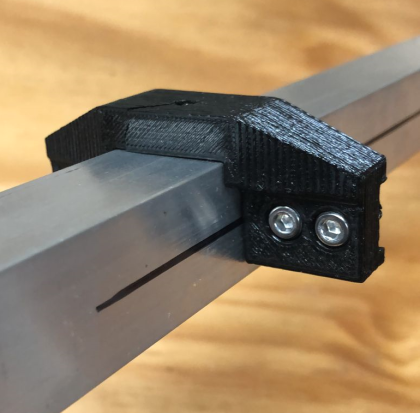
3D Printing the bracket
This is input kindly provided by Duane, KE8BG:
Screenshot from Thingiverse Website
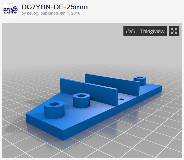
you can download this model here at the 'thingiverse website' https://www.thingiverse.com/thing:2745770


This Bracket was printed using ABS filament with 45% infill.
tnx Duane!
Note: I myself, DG7YBN have zero experience with 3D printing (though I would love to have some, hi).
So I am afraid I cannot help with questions about what filament to use or other 3D printing issues.
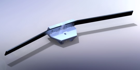
I can draw in 3D though. Below find some brackets I have drawn.
Which Duane, KE8BG kindly converted from .stl file to Tinkercad
and uploaded them to his account on Thingiverse.com, tnx!
3D CAD with .stl file export

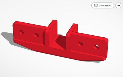
• DG7YBN drawn bracket for 20 x 20 mm boom
Screenshot from Thingiverse Website:

you can download this model here at the 'thingiverse website' https://www.thingiverse.com/thing:2757505
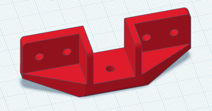
• DG7YBN drawn bracket for 25 x 25 mm boom, rev. 1
Screenshot from Thingiverse Website:

you can download this model here at the 'thingiverse website' https://www.thingiverse.com/thing:2757500
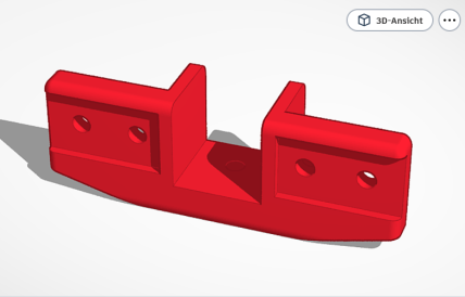
• DG7YBN drawn bracket for 1 x 1 inch boom
Screenshot from Thingiverse Website:
![]()
you can download this model here at the 'thingiverse website' https://www.thingiverse.com/thing:2757508
• DG7YBN drawn bracket for 1 inch round boom
Screenshot from Thingiverse Website:

you can download this model here at the 'thingiverse website' https://www.thingiverse.com/thing:2757512
3D printout of a DG7YBN drawn bracket by David, ZR6DLG and John, ZS6JON

Upright Blade Dipole for UHF
This is what same time Joszef -Joska-, HA5CW and Kazuo, 7L1TIG came up with:
An upright version of the 'Blade Dipole'. 7L1TIG so far built 3 measured 70 cm Yagis (GTV 70-4m, GTV 70-7n, GTV 70-11w)
with that dipole and his feedback shows it is working nicely as well.
The dipoles at 7L1TIG are made from a strip of aluminuim 10 x 2 mm. Find a very smart, because simple and effective
solution in the photo below. The mounting bracket is a stretch of a plastic profile:

Kazou made a whole set of websites about small DG7YBN Yagis.
A very clear and methodic work. I recommend this to read. Use a free website online translator.
After 3D printing became available and popular I decided to draw STL files
for a bracket holding a 10 x 2 mm sheet as dipole on a 20 x 20 mm boom.
And for that a supporting holder for the coax as well.
Bracket for upright bent UHF dipoles from 10 x 2 mm flat strip when elements are mounted ON a 20 x 20 mm boom:


Supporting holder for the coax, any 10 mm type as Aircom, H2000, H2010, Ecoflex ...

Bracket for upright bent UHF dipoles from 15 x 2 mm flat strip when elements are mounted THROUGH a 15 x 15 mm boom:
Bracket for upright bent UHF dipoles from 15 x 2 mm flat strip when elements are mounted THROUGH a 20 x 20 mm boom:
Bracket for upright bent UHF dipoles when elements are mounted THROUGH a 1 x 1 inch boom:


This bracked 3D printed and mounted onto a GTV 70-21n Voshkod by ZS6JON:
Download the .STL file for printing the bracket for a 1 x 1 inch boom, reinforced version:
Download the .STL file for printing the bracket for a 1 x 1 inch boom, reinforced version, with larger width of recesses for dipole plates if 3D printer does not behave:
Wire Shoe Joint Bent Dipole
Here is a piece of work that Aage, LA4ZH developed.
Getting the bending angle right is one task. Getting the dipols angle adjusted for trimming is even more a challenge.
With this solution you have a method at hand that makes it easy, give you have the right size cable shoes.


Blade Dipole for VHF
What does nicely on 432 MHz does on 144 Mhz as well.
The only setback is the sheer size of such a thing? Not at all. Take a look at this Blade Dipole for 2 m by Wolf, DF7KB:
Photo and description: DF7KB, tnx Wolf.


The aluminium stripes are t = 5 mm. Width mid section approx. 50 mm, arms approx. 30 mm
Note: the Balde Dipole needs to be shorter then the thin tube made dipole. 10 percent is just a rule of thumb. Actual shortening factor depends on design and width of aluminium stripes.
Special gimmick is the adjustabel position of the dipole by fastening the base plate to boom with rectangular U-Bolts.

And the full X-pol GTV (a shortened 2-14w) on Wolfs houses roof.
Bent Dipoles made from Aluminium Tubes

The transformation ratio depends on the bending angle given by distance a-b.

3D Printing of Brackets for VHF Yagis with Elements through booom
Early May 2020 John, ZS6JON asked me for a 3D printable VHF version of the brackets I had drawn for 70 cm GTV Yagis.Which I found a very sensible idea, so here they are;


Bracket for Bent and Straight Dipoles for 2 m for square booms 20 x 20 mm and 10 x 1 mm tube
| • Drawing of this bracket as PDF |
|

Download the .STL file here
Bracket for Bent and Straight Dipoles for 2 m for square booms 25 x 25 mm and 10 x 1 mm tube
| • Drawing of this bracket as PDF |
|

Download the .STL file here
Geometry Configurator: from straight tube to bent ends
Bent DE Online Calculator for mechanical production of a bent dipole.This online calculator computes the cutting length for the straight piece of tube per dipole arm.
|
Note: BC and SBC add to the tips at part "c" of the sketch.
|
✱) BC on a dipole? Read more here

|
Attenzione!
However, the bending angle is crutial for impedance tranformation and so for the Yagis feed point impedance. Most bent dipoles need to be adjustment in the real Yagi as neither nec2 nor nec4 kernel get the simulated impedance absolutely right! |
Read how to trim a bent dipole Yagi here
Driven Element Center
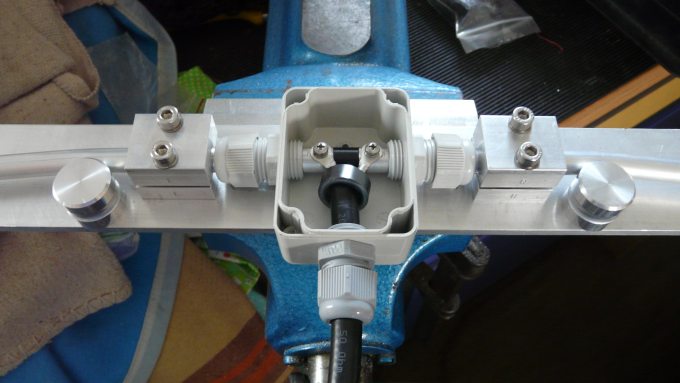
Example Drawing of how I make the Driven Element Center housing box on a 144 MHz 5 elem. Yagi.


The bent DE parts before assembling

 • Use 10 mm spacer made from plastic

 • Use a small plastic box. Use a material that does not contian black fillers.
   I use ABS plastic boxes made by "Bopla" or Fibox".

 • Use plastic cable glands for feeding the tubes through the boxes side walls and keep them in place
   Glands M16 will be fine for 10 x 1 mm tube. M12 fitts 8 x 1 tube

 • M12 equals PG7; M16 equals PG9
   M12 thread is 12 x 1.5 with core hole diam. 12.5
   M16 thread is 16 x 1.5 with core hole diam. 15.2
   Same core hole diameter applies to PG glands but other threads with PG chamfers are uses
   However mounting hole clearance is 12.7 mm for PG7 and 15.4 mm for PG9

 • Cut threads in boxes walls if you have a right size tapper tool.
   This will save space the nuts would need and brings down bores height by 4..7 mm.
   See below ...
Attenzione!
Drill hole for cable glands as low as possible - just scraching the bottom of the box is best.Since any offset between DE and element plane will deteriorate the elevation radiation pattern
Attenzione!
Soldering coax ends to cable eye is done BEFORE fastening the tube-piercing screws fully.

Using a conventional Pipe Bender
Even the close to the inner end bends can be done with ease using a simple pipe bender:
Thomas, M0ABA demonstrates this, see the mark on the scale? Which is to get both sides bent similar.


Bending Tool
Take some wooden board of slightly larger thickness then the to be bent tube.
Here I used 'OSB' industrial plate, t = 15 mm
1.  Cut a square piece of 150 x 150 mm roughly

2.  Draw a circle line (radius 150 mm approx.)
    you might use a kitchen dish) and prolong with straight
    lines (blue lines) aside

3.  Cut along that line with your jigsaw so that you produce
    a simple punch and matrix pair

4.  Make two side plates, fit matrix and sideplates,
    bore through and join with long screws.

- Ready -
Attenzione! ... mind the aluminium tubes spring back and add reduce radius if needed.

Bending tool ready for action

Make a 1:1 sketch of your DE on cardboard and bend the two tubes, leave inside ends stick out some excess millimeters and cut when all in shape.
This format of bending tool is suitable to bend from 8 ... 15 mm tubes. Use slightly larger radius and hard wood in t = 18 or 20 for 18 mm or 3/4".
Bent DE adjustment bench
Adding high precision by refering to a measurement bench ...

Actually not a big deal to build this bench is a help in adjusting both sides to same angle
in case a post trim is necessary or if you want to do many different bent DEs without taking
to 1:1 cardboard sketches every time.
 	• Base is an OSB plate

	• Mount four blocks of wood enclosing the DE box tightly
	  serving as a center mark

 	• Add rulers left / right side; zero is on hight of DE boxes zero ie. bores
A Semi Professional Adjustment Bench - an outstanding mechanic job done by Jörg, DL2VL
A bent dipole jig - another nice job done by John, ZS6JON


73, Hartmut, DG7YBN