-
• Main Page
- • Home • Building
-
- Boom CorrectionIntro to Boom Correction and complete Collection of Factors

• DG7YBN semi-insulated on Boom
• DL6WU / G3SEK formulas and charts in detail
• DJ9BV insulated through boom
• I0JXX insulated through boom
• K1FO insulated through boom
• VE7BQH Cushcraft & Cudee on Boom
• Intro to SM5BSZ's BC.exe
• Microwave BC numbers
• Model Segmentation to real world frequency issues
• The BC-Excel Yagi Element Configuration Tool Download- Symm. & BalunsSymmetrising Devices from Sleeve Balun, F9FT Tube, EMI, G0KSC, Pawsey, 50 ohms Quarter Wave Line to 12.5 and 28 ohms DK7ZB Match ... plus Test Equipment - the RF Current Meter
- Phasing & Matching LinesHow to measure coax stub lines, produce coaxial impedance transformation lines, Baluns and how to stack and match with coax lines
- Howto - Bent DE
How to bent a GTV Yagi DE with a simple selfmade tool:
Bending aluminium tubes by hand leads to buckles and brocken tubes. So I show what a simple selfmade tool looks like. You will need just a piece of wood, a few minutes and a jigsaw to produce one.
It will make the job much easier.
DIY - Bending Tool

- Building a YagiA collection of building hints - from DE-Box to bending Support Struts and mounting Elements
- Boom StrutsA collection of building hints - Planning and bending Support Struts and making bending tools
- Scaling Yagi ElementsHow to scale complet Yagis in Frequency and Element diameters from one dimension to another by hand
- Boom Correction


Driven Element
Transformation & Symmetrising Coax Lines
Full Boom length vs. electrical length
Elements & Insulators on Boom
Elements & Insulators through Boom
Efficient Element Cutting for a 4 x 2 m XPOL Arrray
Building for 70 cm
Converting Units
Tools
Struts and Supports
Driven Element Center
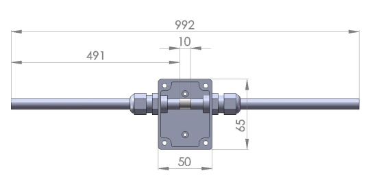
Example Drawing of how I make the Driven Element Center housing box on a 144 MHz 5 elem. Yagi
Some details and hints
 • Use 10 mm spacer made from plastic

 • Use a small plastic box. Use a material that does not contian black fillers.
   I use plastic boxes made by "Bopla" or Fibox" made from UV-stabilised ABS .

 • Use plastic cable glands for feeding the tubes through the boxes side walls and keep
    them in place. Glands M16 will be fine for 10 x 1 mm tube. M12 fitts 8 x 1 tube

 • M12 equals PG7; M16 equals PG9's inner diameter
   M12 thread is 12 x 1.5 with core hole diam. 12.5
   M16 thread is 16 x 1.5 with core hole diam. 15.2
   M20 thread is 20 x 1.5 with core hole diam. 18.6
   Same core hole diameter applies to PG glands but - being metric - other threads with
   PG chamfers are in use. However mounting hole clearance is 12.7 mm for PG7 and 15.4 mm
   for PG9

 • Cut threads in boxes walls if you have a right size tapper tool.
   This will save space the nuts would need and brings down bores height by 4..7 mm.
   See below ...

|
Attenzione! Drill hole for cable glands as low as possible - as narrow as scratching the bottom of the box is best. Since any offset between DE and element plane will deteriorate the elevation radiation pattern - plus - depending on design but very likely shift the resonance frequency of your Yagi by several 100 kHz depending on how much offset is given. |
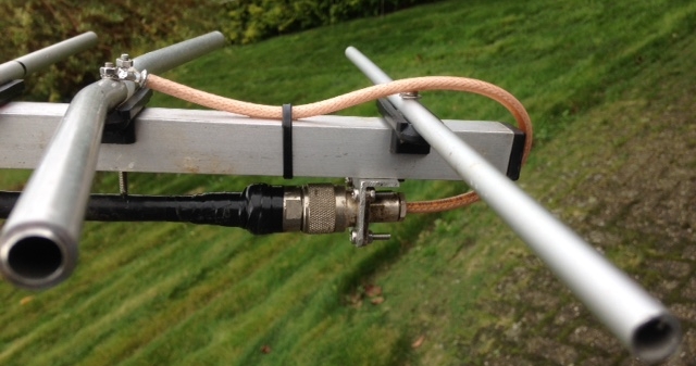
Below is a Photo of the opened DE-Box. The coax used is MIL-quality RG58. Good enough for may occasions, BUT it has to be MIL-quality. The shown split open coax ends are about max. length that I would tolerate. Note the little ferrite core. It is an add-on to the Quarter Wave Line that is grounded to boom as shown further down on this web site. That arrangement makes a simple and effective symmetrising member for 50 ohms direct feed. See Phasing & Matching
|
|
Attenzione! Soldering coax ends to cable eye is done BEFORE fastening the tube-piercing screws fully. If you fasten the eyes before soldering you will need much more heat with weakens the coax PE and might end in deformation. |


Terminology: Element Plane and DE Offset
On a common build Yagi-Uda antenna all the parasitic elements are 'in line'. They are on same height. Either over booms face in case of on 'On-Boom' build with insulators or spacers - or mountend through the boom. We could lay a piece of cardboard onto the elements : what we now see is the 'Element Plane'.
With building the Driven Element (DE) comes the necessity to feed it. And to give mechanical stability to the split tubes at the feedpoint as well as to shelter that part and the split coax from rain. So the DE is mounted to the boom using a plastic box or two insulators either side of the split tubes, all mounted on a holding plate. As both box or plate plus insulators add height over boom to the DE position in relation to the element plane these arrangements cause an offset between elements and the DE.
• Use small boxes, in case of mounting plates : use minimum width needed for sufficient mechanical stability
• When using insulators with little offset heigth arrange the DE tube feed through bores in plastic box as low as possible

The effect:
Commonly Yagis are being simulated just without any offset of the Driven Element. Here radiation pattern and VSWR chart show nice numbers. The real world built takes tolls by means of Boom Correction, an offset of the driven element, an adapted position of the D1. Even with supposed to be small changes only the radiation pattern of the real build easily looks as if belonging to a different antenna ...
How a displacement by mere -24 mm spoils the pattern of an appart from that detail well designed 432 MHz Longyagi. Blue = Pattern with no offset; black = Pattern with dipole being 24 mm below elements
Boom Correction applied to Driven Element?
Before you think that you will never make it through is kind of 'Rocket Science' and quit building your own Yagi let me tell you that I am writing all this down just to help in understanding the mechanisms.
If you simply want to build a sound antenna go straight down to "# Finally ... Conclusions".

The DE is subject to influence of the near by boom as any parasitic element is. Consequently we have to think of a Correction Factor for it too. As the Driven Element is influenced by a number of further details not to be found on the parasitc elements we have to take them into account one by one:
# 1: Segmentation BC (SBC)
Any antenna model using high segmentation will need a slight correction on that. This is no Boom Correction yet, but a general model-to-real world conversion add-on. So, we need the SBC added to the DE's length in any case.
For details on the Segmentation BC look here
# 2: Boom Correction vs. Clearance to Boom
If the DE is absolutely in plane with the elements it needs same BC to be applied. Only that this will seldom be. Most ridgid DE-boxes will not allow to place bores to feed the DE through that low. Especially not, if we seek a good fastening of the aluminium tubes by applying cable glands as described. Therefore I advise to place these bores as close to the boxes bottom as possible and use no washers for the glands but cut threads into the plastic. Radiation pattern and SWR will suffer slightly with every millimeter the DE is out of element plane.
# 3: Box Correction
Any DE-box, cable glands or whatever will be used has its own dielectrical constant. Consequently that lump of material will interfere with the DE's length to the amount it puts down, even if it may "only be plastic". Watch out when using metal boxes or black plastic with unknown HF properties. If it gets hot in the microwave quickly, drop it ... .
Chose a box as tiny as you can or you most likely need to add up to several millimeters to the DE's length
# 4: Coax Connection at Center Point
Any excess length of the split up coax ("pigtails") will add to the DE's electrical length. Open lengths of almost 1 inch, as often to be seen, are not what is suitable with the original DE length! Try to keep the open wires as parallel to the DE's tubes as possible instead of having them almost rectangular to tubes.
For details on how BC or actual DE's length might be obscured see here
# Finally ... Conclusions:
Some of the above factors virtually prolong others shorter the Driven Element. They might compensate each other, but if you stick to the guidelines below you should be on the safe side. Do build using a tight, flat box of approx no more that 50 x 50 x 35 mm on VHF/UHF, use "light" materials, very short connections, start with the BC given for the parasitc elements in case your DE will not be more than approx. 2..3 mm out of element plane. Else lessen the applied length correction on your dipole unless you have chosen a relatively large box. All the little influences no. 1 - 4 mingle to a specific necessity of length correction for optimum results.
Well, you could of coarse start tuning the Yagi with an excess length on your DE and cut away until the SWR is where it shall be. But that would not be so smart, would it? And remember that when around target frequency most Low Temperature Yagis will show a increase in SWR dip frequency when the DE is shortened and vice versa!

|
With the Box shown on the photos above and below with DE being just 3 mm out of element plane I use the full element BC (BBC+SBC) on the DE with good results. |
Grounding Transformation & Symmetrising Lines
The image shows a 50-to-50 ohms Quarter Wave Line, grounded via an N-cable-flange-bushing and a mounting bracket
made from a sheet of 2 mm thick aluminium.
• Photo & make: DG7YBN (the ferrite core is inside the box, see § Driven Element Center)

• Photo & make: HA1VQ at HA1KKY, Radioclub Köszeg (tnx Jozsef).
Note the ferrite core on left side, a very good position as close to the splitted coax as possible.

• Next three photos below & make: DL1VL (tnx Jörg) - H2010 and heat shrink tube.
The ferrite core is inside the box, see § Driven Element Center.


Mounting brackets
| Photo & make: DG7YBN | Photo & make: HA1VQ at HA1KKY, Radioclub Köszeg |
|

|
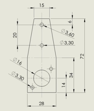
Attenzione! Drill holes before bending the bracket!
1.  Bending line is at 34 mm, just where the chamfer starts
    Bend by approx. 90 degrees

2.  Lower bore on chamfered part is for M3 (Ø 3.3 mm).
    That screw acts as fastening for DE-Box and mounting bracket

3.  Upper bore on chamfered part is for 3.5 x 16 mm self tapping screw
    That screw shall be driven into the boom to give best electrical contact
And an example employing quality PTFE coax RG - 142 B/U, a clip on ferrite core and strain relief cable gland
showing the bracket pre bending. The dashed line shows where to bend:


Please Note
It is understood that the real velocity factor of a plastic insulated coax line at VHF/UHF range is a function of designated frequency .
Owen Duffy at http://owenduffy.net/blog/?p=5622 writes:
"Like all narrowband / tuned common mode chokes, tuning to the desired frequency band is essential to their effective operation."
Read Owens full blog here
It is exactly for this reason, that I write about how to measure coax line lengths properly.
Please read the preface of both subsides before making your own Quarter Wave Symmetrising Member
here
and here
A slight Flaw installing a Quarterwave Line
What is this about? We have a standard DG7YBN Quarterwave to gnd Symmetrising Line
which does not behave as planned. Why so?
Note the cable strap that ties the coax to gnd after approximately 2 inch.
Furthermore there is a strange second dip at around 438 MHz that should not be there.

The 2 inch to gnd strip mixes with the 'should be length' and supposably acts as 1/12 wl stub for the 438 MHz somehow.
So now: unleashed ... as it shall be


The lesson to be learned?
> If you feel like supporting the 1/4 wl line ... use plastic stand offs or alike.
The final question:Q: Why does the usual way of leading the 1/4 wl stub in a bow down the boom while it touching the boom at approximately half length not disturb the Retrun Loss plot?
A: Because lengths far off anything 1/12, 1/4 or such are not critical. They are to far away in resonance frequency to do any harm, to mix with the actual frequency.
But: whenever in doubt about plotting results now take the possibility of the above shown effect into account.
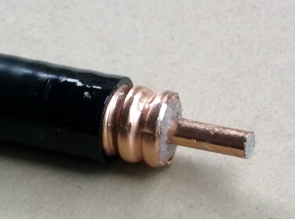
A serious QRO Quarterwave Line
The 7/16 bushing is a Spinner BN 710368

The small length was kindly provided by Kabel Kusch, Dortmund, DL / tnx Mrs. Kusch!


Ferrites in place (Amidon FT 114-43, 2 pcs) and centered with thin plastic stripes
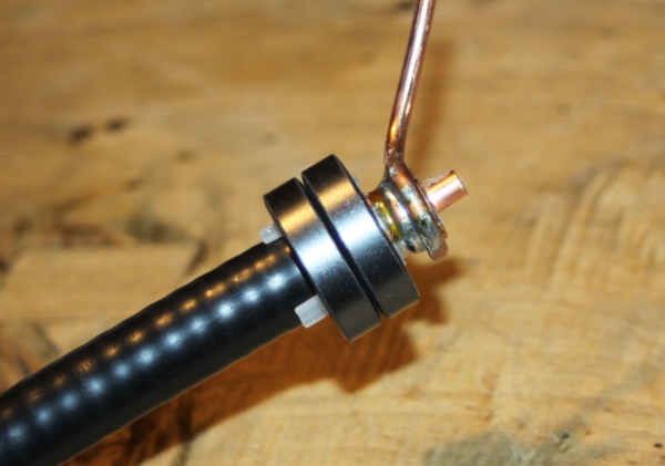
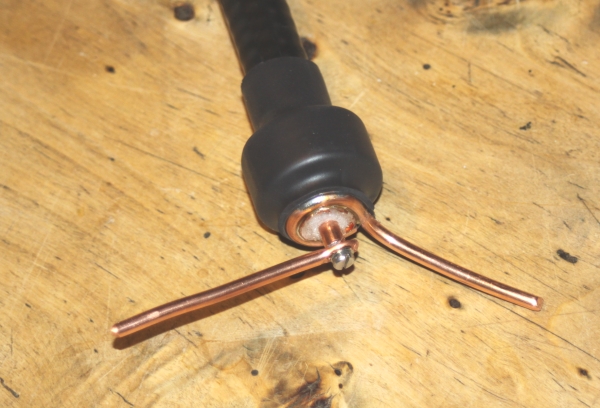
Connection copper wires are 6 mm2 or approx. Ø 2.7 mm
The inner is attached by cutting an M3 thread into the Cellflex core and using an M3 x 10 screw.
For this the copper wires end is flattened by pressing it in a vice.


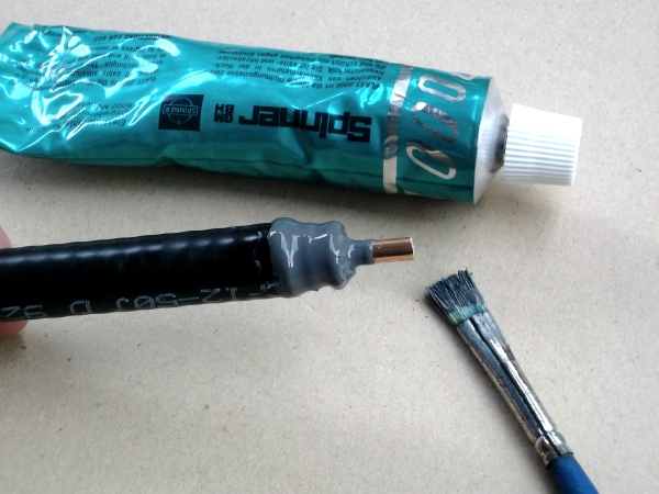
Sealing the open ends, part 1
Spray coating the open surfaces with special clear coat
• solderable final shielding layer coating for electronics, antennas ...
• withstands 25 kV
• durable, elastic layer

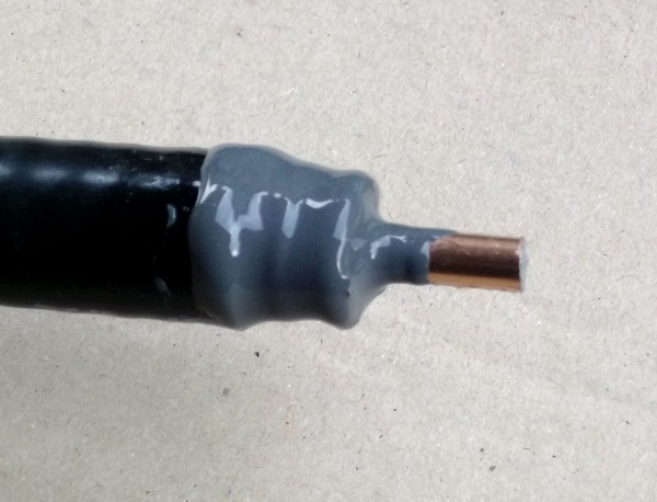
Sealing the open ends, part 2
On the dry clear coat layer I applied Spinnerplast 2000 with a medium hard paint brush
Real world Quarterwave symmetrising line trimming
• How accurate should the lines length be?
For the 2 m band we face a factor of round about 3 mm / 1 MHz for a 1/4 λ coax line resonator.
To link this with the factor for Yagi elements: A 1/2 λ element has a (BC relevant) factor of 5.85 mm / MHz.
The 1/4 λ resonator is 'double sharp' plus the overall 0.66 ... 0.8 of velocity factor per coax insulator material.
The reciprocal number of the velocity factor gives ~ 1.25 ... 1.5 as additinal 'sharpening factor'.
So that we end up with a 5.85 mm / 2 x 1 / v-factor = 5.85 mm / 2 x 1.25 = 3.65 mm per MHz for a
foam insulated coax like Aircom, H2000 etc. on the 2 m band. For the 70 cm band it is roughly three times that.
On 70 MHz less than half.
Now we can imagine what it means to cut a coax transformation or symmetrising Quarterwave Line using
the factory given v-factor for 1 MHz only and ending up with an line, that is ~ 7% or 21 mm longer than it should be.
• Lets take a closer look at the details we have to face in practise when integrating a Quarterwave
symmetrising member into a Yagi-Uda antenna:
The sketch below is but an equivalent circuit scheme

be taken into account for the real world picture. As in reality they are not idealised. They have their
non infinite lengths and inductivites / capacitances. Which merge with the lengths of dipole and QW-line.
• Current paths inner conductor / outer briad
Further we have to tell apart the way into the dipole, with the RF taking the 'inline route' through the
coax versus the return way on the outside that any common mode current will try to take. Now we do have
a ferrite core in place to produce an effective barrier due to its high resistance on this path. But for
any currents'ambition' to take the outside route if will be welcome to have that as close to a real 1/4 λ
as possible. Since this path is somewhat shorter and covered in less plastic (v-factor of this path) the
length of the mounting bracket may help to match it. Find more on this topic in next chapter.

They have an inseparable bond.
The mechanism:
taken from my Dubus 2/2010 Artikel "Applied Conversion of Segmented Wires from NEC2 to 144 MHz Yagi Elements - Part 1"
" '[Quarter Wave -] Feedline and Antenna must be in resonance as a whole. [
] Therefore one for instance can
eliminate the resulting reactance of a too long or short measured radiator by extending or shortening the
[Quarter Wave -] feeding line [ ].'
Karl Rothammel, Antennnenbuch, 5.3.2 Tuned transmission line
For sure we do not want a detuned DE as a result of having a prolonged or reduced quarter wave line length so
please tune the line carefully with a grid dip meter. Make a good and broad connection to the boom and no pigtails
at the DE side please."
• Read more about how symmetrising line, dipole
and wave guiding structure work as a package
• Now what does that mean in practise?
take a break
Every inconsistency in the diameter of a coaxial conductor can cause a sectioning for the passing wave.
Which here is the cut between the end of the feeding line and the start of the quarterwave line. This point
naturally is also defined by the grounding point. But here we are reviewing details of a real build.
Below I show a sketch of how I build my reference lines. Here it is clear, where the "cut" is to be found.
But what about a real built employing a N-cableflange-bushing? Here we yield the "cutting break" somewhere
around the end of the inner pin. Consequently it pays off to integrate that bushing into our measurment.

(i) How to get the dipole connection side right?
I am frequently being asked whether to measure a QW line length with or without ring eyelets soldered on.
I tend to say, it is not that an important question as long as the package of QW - line & dipole works.
Both have to fit their own frequency responses of 1/2 respectively 1/4 λ. The border line of which
millimeter belongs to what device can not be drawn that sharply in a real world build.
The prime intention of measuring / dipping the QW - line right is to prevent you from starting into this venture
with a much less fitting line length. And by doing this the right way have much less unwanted load on the QW-lines
partner, the dipole as to be 'corrected' span width.
Below I show how the fully equipped QW -line can be measured.
The upper sketch shows core and braid connected on the dipole side for inductive coupling to the VNA / dipmeter
The mid sketch shows the bushing shortened with a piece of soldering wire for a capactive coupling to the VNA / dipmeter

We can short cycle the QW - line at the bushing end and measure with the bracket on.
I use a bit of soldering lead for that.It works out either way twisting the core and shielding
on the dipole side together.
However, trimming the dipole to exact length remains. For reasons like the adaption to the dipoles
plastic box or plastic holders of the dipole arms. With this we will balance the inevitable amount
of delta in the dipoles spanwidth. Which works on the system, the pairing of dipole and QW -line.
Summarised
... having trimmed the QW - line properly we will have much less deviation to the designed dipole
spanwidth and thus a build whose parameters are much closer to the simulated design
How large must my ferrite core be on a quarter wave symmetrising coax?
A large Balun for transforming Impedance on shortwave

On the Quarter Wave Line a much smaller ferrite core will do.
Why? ... because it does not deal with the full TX power here. It will only deal with what wants to leave the Driven Element as common mode current. Which depends on how symmetrical DE and Yagi and enviromental influences are in the very case of your build. The more towards ideal symmetry the DE and Yagi are build, the smaller it theoretically can be.
I1 and I2 excitate the Driven Element through the feeding coax. A deranged symmetry by missing length of right arm of the DE causes a fraction of I4 to return as I3, which tries to 'escape' as common mode current on the outside of the coax.

• Case B: Plastic Dielectricum, oridinary coax, if inside is 1/4 lambda outside is too short per 1/v-factor.
• Case C: Blocking common mode current that sees lower resistance per not 100 percent 1/4 lambda on outside
I have used the Amidon T50 size with up to almost 200 W on 144 MHz with no thermical problems at all.
Ferrites
Ferrite cores and beads are classified by material and sizeExample Amidon FT 50 B-43 ..."50" = size, "43" = material
Size
Size Amidon T37 or T50, inner diam. = 5.21 / 7.70 mm fit RG58 and RG142 B/U Teflon coax.
Size Amidon T80, inner diam. = 12.6 mm fits RG213 coax, Aircell ...
• Some Coax Cable Outer Diameters
PTFE insulated RG 142 BU = 4.9 mm
H2005 = 5 mm
RG 213, H2010, Ecoflex 10, Aircom 10 = 10.2 .. 10.3 mm
LCF 12-50 = 16.2 mm (0.64 inch)
Materials
Material 43 is for blocking VHF/UHF frequencies.
Material 43 is an industrial standard from NiZn for blocking 20 - 300 MHz.
Material 31 seems even more suitable for blocking VHF RF but may be hard to get.
Material 31 is quoted as 1 - 300 MHz from MnZn with good broadband impedance.
Material 61 seems very capable of blocking at UHF but may be hard to get as well.
Material 61 is quoted to cover 200 MHz - 1 GHz and is also made from NiZn.
• A coarse chart showing Impedances vs. Materials for a given size of ferrite core

And there is also a Color Code at Amidon:
Example: Code T50-0 (color code: brown) covers 50-300 MHz
A good choice are the following cores:
• Make: Amidon
FT 50 B-43 inner diam. 7.9, outer diam 12.7, length 12.7 mm (approx EUR 3 pp.)
FB-43-5621 inner diam. 6.4, outer diam. 14.3, length 28.6 mm
FB 43-1020 inner diam. 12.7, outer diam. 25.4, length 28.2 mm
• Make: Fair Rite
Fair-Rite "Snap-It" 04XX164281 inner diameter 6.3 mm with XX = material 31, 43 or 61 for UHF appications
Fair-Rite "Snap-It" 04XX164181 inner diameter 12.7 mm with XX = material 31, 43 or 61 for UHF appications
• Here is a Microsoft TM Excel by Dani, YO5LD
which he kindly offered for this website. It gives a nice overview on Fair Rite Ferrite Cores.
This file holds links to Co. Fair Rite. Note that I do not feel responsible for any possible inconventience resulting
by making use of these links. Use this file on your own risk.
Link to download/open this MS Excel:
See details here
http://www.fair-rite.com/wp-content/uploads/2016/04/Cable-Core-Flyer-FINAL.pdf
My thanks got to Serge, F5JTM who pushed me and provided more details about ferrites and materials to enhance this chapter!
Mechanical Boom Length: ... DO NOT mount Elements on edge of boom please!
Do for no reason mount Reflectors or last far out parasitic element right onto the cutting edge of the boom tube.

Why?
Because whatever BC must be applied, it will meet unconditinal properties if the boom suddenly "breaks away" underneath the first or last mounted element. As we designers see what the right electrical length of Reflector and last directing element do to the pattern it would be be out of place to spare 2 x 30 mm of boom tube and spoil the radation pattern instead.
Just when using high enough insulator mounts like "Stauff Clamps" as per G0KSC or "Paraclips" per G4CQM you might get away in cutting sharply with a "black eye only".
Ok, understood, but what offset should I use now?
I can not provide absolute measured and numbers but a brief simulation that F6DRO made for me with advanced HF modelling software (TNX Dominique!) showed a very clear influence of a sharply cut boom end up to approx. 30 mm on 432 MHz. I would suggest a minimum of 30 mm on 144 MHz and 432 MHz will prevent most damage.
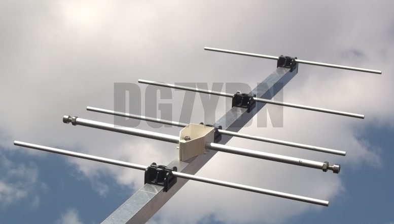
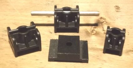
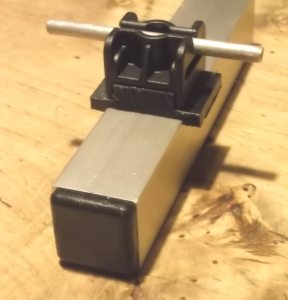
1. Element mounting above Boom with Standard Insulators (WiMo, Konni, Nuxcom, 7arrays)
Mounting of 8 .. 10 or 12 mm Element

|
|
8 x 1 mm tube as Element on 25 x 25 mm square Boom

if you do without you may use a washer M3 size instead.
15 x 15 mm boom with 8 mm element = > screw M3 x 30 mm
20 x 20 mm boom with 8 mm element = > screw M3 x 35 mm
25 x 25 mm boom with 8 mm element = > screw M3 x 40 mm
Other parts: use washers and self locking nuts (whenever available)
M3 washers, large (Ø 9.1 mm) - to place between screws head and element (in case of not using reinforcing plate)
M3 washers, ordinary (Ø 7 mm) - to place between nutand boom
M3 self locking nut
UHF building style with 6 mm elements


|

|
25 x 25 mm boom with 6 mm element = > screw M3 x 35 mm
Other parts: use washers on screws heads
M3 washers, large (Ø 9.1 mm) - to place between screws head and boom
What Boom Correction to apply?
see here
What Element Diameter do these Insulators serve & where to buy?
These insulators can take from approximately 5 to 12 (... 15) mm elements due to the v-shaped chamfer the elements settles into. The basic design is all the same for all sizes. Just the boom slot is different.
Where to buy?
Ok, this website is not so much about commercial advertisements but look here:
(1) nuxcom.de Shop run in DL by Attila, DL1NUX, does Paypal and international shipping,
Nuxcom runs metrical and Imperial boom measures.
(2) wimo.de Shop run in DL by Volkmar, DF2SS, ... who does not know WiMo?
... international shipping and all it takes. Ask for DB6WY if you have specific questions on
insulators and antenna parts. WiMo runs metrical boom measures only.
WiMo order numbers:
23042.15 = square boom 15 x 15 mm
23042.20 = square boom 20 x 20 mm
23042.25 = square boom 25 x 25 mm
23042.30 = square boom 30 x 30 mm
23043.25 = round boom 25 x 25 mm
23043.30 = round boom 30 x 30 mm
Be thoughtful and order the long shaft M3 screws with the insulators.
As it is quite unlikely to find fitting lengths like M3 x 40 mm in a DIY.
2. Element mounting above Boom with Insulators from SM7DTT
Demonstration & 432 MHz Test Yagi (YBN 70-5m)
Photo: on 20 x 20 mm boom
These Insulators are produced by SM7DTT.
They can be bought from him directly. These insulator are available for 20 mm, 25mm using an adapter plate and 12 mm square booms.
• Size for 12 x 12 mm or 12 x 20 mm fit Ø 3.0 mm elements
Cross Sectional Sketch
• The elements are pressed into the slot from aside
• They are constructed in a way that fastening the mounting screw tightens the slot around the element further.
Fastening screws
• M4 x 30 mm fit the 20 x 20 mm boom type (as to be seen on photo)
• M4 x 45 mm fit the 25 x 25 mm boom type incl. adapter plate
• M4 x 50 mm fit the 30 x 30 mm boom type incl. adapter plate
Element clearance from boom
• Space between booms upper face and element is 7.5 mm for the 20 mm type.
• Space between booms upper face and element is 15.3 mm when adding the adapter plate for 25 mm booms
• Space between booms upper face and element is 16.9 mm when adding the adapter plate for 30 mm booms
• Space is 8 mm for the small size 3 mm elements on 12 mm boom type


These Element holders can be obtained from SM7DTT
Mail to:

Verification of BC numbers is on its way, see 432 MHz 20x20 mm here
3. Element mounting above Boom with Insulators from LA4ZH
70 cm Test Yagi


Photos: 6 mm element, on 25 x 25 mm boom (left) 20 x 20 mm boom (right side)
Material: reinforced PA (Polyamide) with 30 percent glassfiber
can be ordered in two versions for all geometrical versions: with and without carbon black filler.
The white on is PA6 GF30 'natural', the black one is with carbon black filler = PA6.6 GF30
Fitting boom sizes:
• Metric Version:
Square Boom 16x16, 20x20, 25x25, 30x30 mm
Round Boom 28 mm, 30 mm, Order No. 51300
• Imperial Measures Version:
Square Boom 0.75x0.75, 1x1, 1.125x1.125, 1.25x1.25 in
Round Boom 1, 1.25 in, Order No. 51320
Sketch: Boom face of insulators, by turning 90 degr. on boom it is possible to mount
same element holder on various boom dimensions

All versions fit elements Ø 6 ... 14 mm
Element clearance from boom
• with 16 x 16 & 20 x 20 mm boom => 15 mm
• with 25 x 25 & 30 x 30 mm boom => 19 mm
More information coming soon .....
These Element holders can be obtained from the Norwegian Shop
http://eidolon.no
go to "Antenne elementfeste"
Verification of BC numbers is on its way ... come back to my Boom Correction website in May pse.
Thin Elements mounted insulated through Boom
This method can be seen as in tradition of what is known as "the nylon rivets methode" propagated by DJ9BV. Which he adopted from DL6WU, who adopted it from DJ6NS. The classic way is using elements of Ø 4 mm (aluminium welding rods), holes in boom Ø 6 mm and nylon rivets, Type 61PR800000 (no carbon fillers), Heyman Manfacturing GmbH, 35390 Giessen, Germany
Using easily available plastic parts, 4 or 5 mm (likewise 3/16 in) elements in combination with the advanced BC.exe by SM5BSZ (see my MS Excel 'Yagi Element Configuration Tool') produces leightweight, easy to build but performing Yagis.
This method of mounting elements also suits xpol Yagis as at least both planes or polarities elements are fitted fully symmetrical here.

DG7YBN injection molded insulators with hole for Ø 4.0 mm elements to be pressed into Ø 6 mm holes in boom
These insulators are available at 7arrays.com
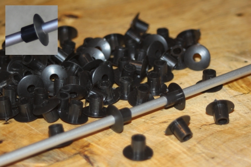

Below: Furniture plugs to cover 6 mm holes. Inner Ø is 4 mm. Fits Ø 4 mm elements when a hole of Ø 3.9 mm is drilled through the top.

Bantam hole plugs "used to fill unused jack positions" in shelfs and alike in Imperial Dimensions fitting Ø 3/16 in elements

A number of prepaired plugs


Mounting Thin insulating Elements through Boom
1. Pre-drill with 3 .. 4 mm drill
2. Use a SHARP drill, in case of the the 4mm insulators by 7arrays that is diameter 6.0 mm
3. Deflash holes, but see that diameter does not get any wider!
4. Drill all holes in boom section and clear its inner from chips, turnings
Now the boom section is ready to mount elements
1. Mark Element center and both sides half outer boom width (1)
2. Push first insulator 1 to mark (2)
3. Insert element into boom
4. Use a push-rod approx. 8 x 1 or 10 x 1 mm to gently press or hammer insulator with ele. in place into boom (3)
5. Repeat on other side (4)
6. Do fine adjustment for element position, if too firm for pushing or pulling use wooden piece and hammer gently
Hints:
i) If insulators are too tight to push, add a drop of washing liquid or similar, a lubricant
ii) If a test insulator fits into boom hole to loosely, drill diameter does not fit
iii) If element fits too loosly you can add a bit of roughness to surface and enlarge diameter at marked zones
by gripping it with a toothed plyers
Cut Plastic Plugs for 3/16 inch Elements from South Africa
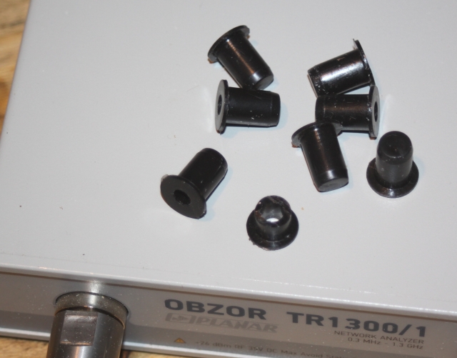
Cut down to 7 mm total lenght, inserted in a drill hole of Ø 7.9 mm in the boom.

YBN 70-5, 4 mm Elem., DE Offset 18 mm

The 70 cm EME 4 Yagi bay of GTV 70-19m at ZS6JON is built with these plugs and shows very good numbers
Rubber Grommets as Element Insulators for portable Yagis

What is rubber?
60 percent caoutchouc / Kautschuk (latex milk),
30 Percent filler materials,
8 percent softener,
rest of 2 percent: zink oxid, sulphur, stearin acid
weatherproofness is good, UV resistance 'very good'
Permittivity 2,5 - 3
Specific ohmical resistance 10xy14,
Electrical strength 10.000 - 30.000 Volt/mm
Typical material for feed through rings is chloropren-caoutchouc (normed as CR) known as 'Neoprene' by Co. Dupont, a synthetic caoutchouc

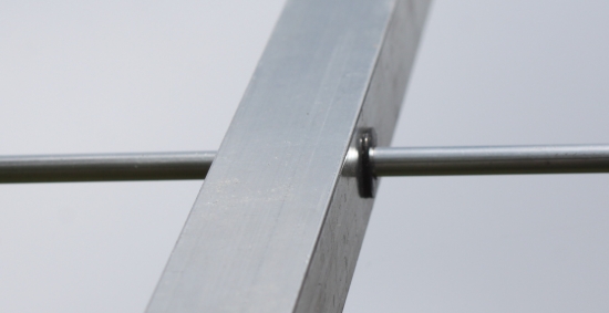
4 mm Elements:
Drilling a hole of Ø 5.5 mm for 15 x 15 x 1 mm booms or Ø 5.8 mm for 20 x 20 x 2 mm booms makes them fit tight with a good ability to push the element rod in and pull it out again.
Being able to push in and pull out the elements in no time with no tools,
(maybe with a little talkum powder?) is a clear advantage for portable use.

You are distrustful? Rubber Rings on UHF?
Alright, I was observant myself.

Using 50 W and this single highly portable Yagi (4 boom sections) they did
8 QSOs, 8 initials, all JT65B, DXCC 7, WAC 2 in just 2 moon paths.
Image: Dan, HB9CRQ
But, it is able to cope with weather, its dielectrical properties are close to PTFE ... and here is a test plot of a YBN 70-5, because of dipole offset of 18 mm from element plane a 432.70 MHz is what NEC computes ... a 432.69 MHz at -60 dB Return Loss .. is that sufficient for your application?


A Dipole for thin Elements mounted insulated through Boom with no Offset
As for a Low Nosie Yagis clean pattern the offset between dipole and element plane is crucial,
and even more so for any x-pol Yagi, with elements mounted through the boom we want a dipole to be same.
Easy being done with a folded dipole, a bit more a challenge with a straight dipole?
Not at all, just look at the following photos ...
Solution: 70 cm
M0ABA built 70 cm GTV 70-4m, this is a Yagi he did several EME QSO's with feeding 60 W only (!).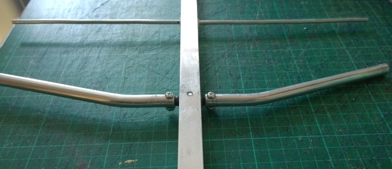
and this proposed dipole mount by M0ABA on the website for the GTV 70-4m
Solution: 2 m
And ZS6JON building same style for a bay of 2 m GTV 2-12n x-pol Yagis

And this is the centerpiece ... note the larger inner diameter.
Boom dim. is 25 x 25 mm here, dipole tube diameter is 9.7 x 1 mm


Connecting pieces for the coax made from copper


Cutting elements for 2 m efficiently
A method to cut all 8 elements needed for 4 bay of 2m xpol Yagis in one go!


Photos on courtesy of OE3NFC - tnx!
Building 70 cm Yagis - Guidelines
A 432 MHz Yagi is on the edge to microwaves. This is UHF - and not VHF anymore!
While boom correction factors reach dramatic numbers the importance to cut elements up to the 10th millimeter grows by factor 6. Here are numbers produced through a lot of real world measurements to proof this:
Freq. [MHz]     Factor [mm/MHz]
   144                5.85
   432                0.92
Consequently the same habitus of using a tape measure to mark the length and cutting elements with a saw most likely will lead to suboptimal antennas. If a consistant 0.9 mm on all elements moves the 70 cm Yagi by 1 MHz, what will a random +/- 0.5 mm due to "sawing accuracy" do to the fine trim of a NEC model?

Another good point is the choice of the right BC and with that sticking to the proposed method of mounting the elements. In any way if neither elements length are within at least 0.2 mm and BC is not fitting as well or mounting method does not fit to BC any trial to trim the produced Yagi is shooting in the dark.
Influence of Endcaps on 432 MHz Yagis if not enclosed in concept
We will test a PVC hose 6 x 4 mm of length 14 mm (on left) and a tiny 4 mm piece of PA6 (on right)

The DUT antenna is the YBN 70-5 with 4.50 mm elements through boom and some DE offset. This is not a particularly 'High Antenne Q' design.Due to element diameter and DE offset simulation and VNA plot are at 433.8 MHz here.
So here is the baseline plot without any caps on.

• Now with those tiny PA6 pieces on D2


• Now with that tiny bit of transparent PVC hose on one side of D2 only

Now imagine what happens when you put on some 'arbitrary' endcaps on all elements without serious correction of the element lengths ...
Imperial Measures to Millimeters
1 inch = 2.540 cm = 25.40 mm.
So 3/8" in millimeters is the fraction 3/8 = 0.3750 multiplied by 25.4 => is 0.3750 x 25.4 mm = 9.525 mm
Elements
3/16"  =  4.763 mm
1/4"   =  6.350 mm
5/16"  =  7.938 mm
3/8"   =  9.525 mm
1/2"   = 12.700 mm
5/8"   = 15.875 mm
Booms
1/2"   = 12.700 mm
3/4"   = 19.050 mm
1"     = 25.400 mm
1 1/4" = 31.750 mm
1 1/2" = 38.100 mm
1 3/4" = 44.450 mm
2"     = 50.800 mm
2 1/2" = 63.500 mm
3"     = 76.200 mm
Tools
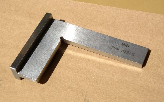
• 90 Degree Angle Try Square Ruler / Messwinkel
• Marking gauge / Streichmaß

• Countersink / Handsenker

• Hand deburring tool / Handentgrater

The Making of ... a Support Strut
Nice Yagi, .. just a bit fragile boom

Nicer with sound strut
The shown strut employs two identical aluminium bars. Dim. 20 x 20 x 1 or 20 x 20 x 2.
Both are bend in identical way on same dye on both sides. That way they are symmetrical in lengths and angles.

A dye made from hard wood

When making the dye
 	• Do not apply bending angles in excess of some 15 degrees.
	  Hardened aluminum might not take more bending without problems.

	• Apply 1 ... 2 degrees more since the bended metal will spring back
	  when pressure is released.

 	• Make ends run out flat for at least some 70 mm.
	  These give guidance and may serve a fixing areas later on.
	  Use outer edge as mark for inserting the square rods edge to edge.

Applying some pressure ... use a large vice.
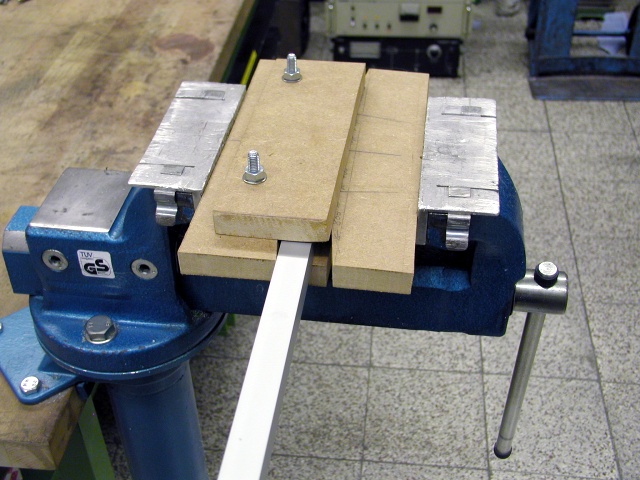
Press until you feel a sudden increase in resistance

... note the spring back make a test on a coarsly made dye and add that angle
before producing your real strut

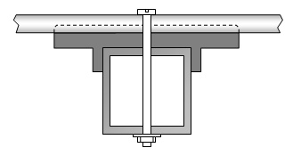
How to stay clear of the mast on 432 MHz and above
|
|
Attenzione! The influence of a pole sticking right thru your UHF Yagi including mounting clamp and all is a serious one. Especially when the mast is not in ´symmetry with the element centres, as must be when attached sideways to the pole tube. As imperfect as a simulated boom tube may be in any NEC program. The outcome shows plenty of pattern deterioration, the more the thicker the pole tube and the larger its sideway offset is. |

|
|
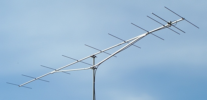
Inspired by the well known 1296 MHz Tonna Antennas I thought of a support strut strong enough to hold a 432 MHz Long Yagi in same style. Using 20 x 20 x 2 aluminium for boom and strut, bolted together with 2 x M5 x 50 screws per side and large washers works fine. |
This strut is bent from a single beam of aluminium to produce increased stability. Bent little by little and adjust stepwise.
73, Hartmut, DG7YBN