-
• Main Page
- • Home
• Antennas - • 432 MHz
- YBN 70-5mA 0.5 m 432 MHz blue print of the YBN 2-5m 50 ohms high F/B direct feed 144 MHz Low Noise Yagi
3D Plot

- YBN 70-8zA 1.5 m high gain 28 ohms Yagi.
A design partly based on the hardware of the WY-7010, turning it into a 8 ele. 28 ohms Yagi with cleaner pattern, +1.8 dB gain and better VSWR.
Azimuth Plot
- YBN 70-14wzTune up your 19 ele. Tonna!
A design based on the hardware of the F9FT, turning it into a 14 ele. OWL with cleaner pattern, +0.3 dB gain and SWR less than 1.2 from 430 to 440 MHz
Azimuth Plot
- YBN 70-14+4wA 3.2 m very wideband 50 ohms Yagi with reflector wall that covers the whole 70 cm band with ease
Elevation Plot

- GTV 70-2wA 0.14 m GTV useful for portable operation and up to the satellit band and handheld activities of any kind
Elevation Plot

- GTV 70-3wA 0.21 m GTV useful for portable operation and up to the satellit band and lower noise stacks of any kind
Elevation Plot

- GTV 70-4mA 0.34 m GTV useful for portable operation up to the satellit band and lower noise stacks of any kind
Elevation Plot
- GTV 70-7wA 0.96 m GTV useful for portable operation up to the satellit band and lower noise stacks of any kind
Elevation Plot
- GTV 70-7nA 1.1 m 432 MHz blue print of the low impedance, yet 50 ohms direct feed 144 MHz Low Noise Yagi introduced in Dubus 1/2013
Elevation Plot
- GTV 70-8nA 1.3 m 432 MHz GTV with high gain but low backlobe volume. Makes a very compact 4 Yagi bay for QRP EME or contesting.
Elevation Plot
- GTV 70-9wA 1.44 m GTV ment to be useful as a vertical stack for contesting or be an ideal small size portable Yagi
Elevation Plot

- GTV 70-10wA 1.63 m GTV useful for portable operation up to the satellit band and lower noise stacks of any kind
Elevation Plot
- GTV 70-11wA 2.01 m GTV ment to be useful as a vertical stack for contesting or be an ideal small size portable Yagi or minimum size EME 4 bay
Elevation Plot
- GTV 70-13mA 2.5 m GTV ment to be useful as a vertical stack for contesting or be an ideal small size portable Yagi or minimum size EME 4 bay
Elevation Plot
- GTV 70-14m2.9 m version of the low impedance, yet 50 ohms direct feed Low Noise Yagi with bent DE introduced in Dubus 1/2013
Elevation Plot
- GTV 70-17m3.7 m version of the low impedance, yet 50 ohms direct feed Low Noise Yagi with bent DE introduced in Dubus 1/2013
Elevation Plot

- GTV 70-18w4.0 m version of the low impedance, yet 50 ohms direct feed Low Noise Yagi with bent DE introduced in Dubus 1/2013
Elevation Plot
- GTV 70-19m4.2 m version of the low impedance, yet 50 ohms direct feed Low Noise Yagi with bent DE introduced in Dubus 1/2013
Elevation Plot

- GTV 70-21n4.7 m version of the low impedance, yet 50 ohms direct feed Low Noise Yagi with bent DE introduced in Dubus 1/2013
Elevation Plot

- GTV 70-23m5.3 m version of the low impedance, yet 50 ohms direct feed Low Noise Yagi with bent DE introduced in Dubus 1/2013
Elevation Plot
- GTV 70-25m5.9 m version of the low impedance, yet 50 ohms direct feed Low Noise Yagi with bent DE introduced in Dubus 1/2013
Elevation Plot
- GTV 70-30m7.3 m version of the low impedance, yet 50 ohms direct feed Low Noise Yagi with bent DE introduced in Dubus 1/2013
Elevation Plot
- GTV 70-34w8.5 m version of the low impedance, yet 50 ohms direct feed Low Noise Yagi with bent DE introduced in Dubus 1/2013
Elevation Plot
- GTV 70-46w12.0 m version of the low impedance, yet 50 ohms direct feed Low Noise Yagi with bent DE introduced in Dubus 1/2013
Elevation Plot

- DL6WU YagisThe DL6WU Longyagi Series
Sample plot: 32 el. plus 4 x reflector
Elevation Plot

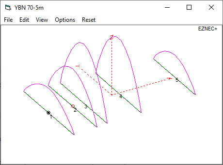
- YBN 70-5m
YBN 70-5m 5 Element Yagi with Conventional Driver
This little Yagi has a high F/B, which makes it quite useful as a contest stack.
The YBN 70-5m is the very pilot model which was used to derive all the "On-Boom-BC-Factors"
(see Dubus 1/2011). It has been measured about 40 times using various boom dimensions and
element lengths.
Current Profile
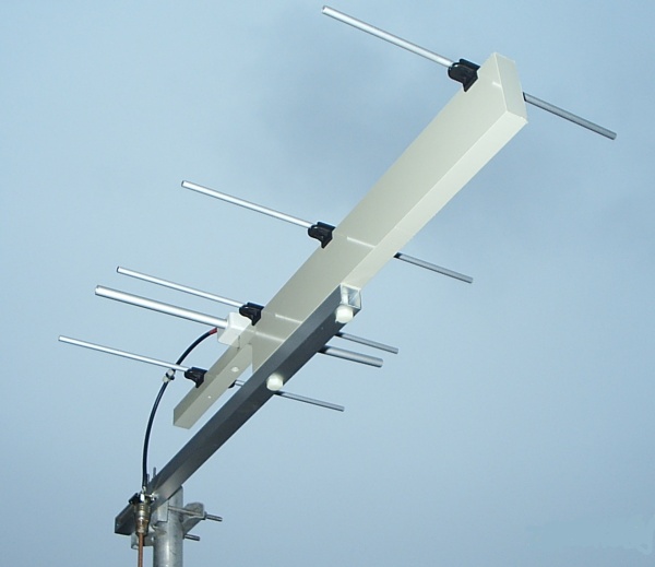
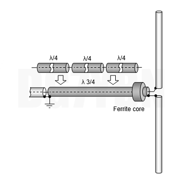
The photo below shows the measurement-Yagi on PP-plastic boom. See the symmetrising 3/4 λ coax line
connected to "gnd" using an n-bushing screwed to the provisional aluminium sub-boom to mount the PP-Yagi to the mast?
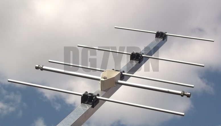
• A lightweight YBN 70-5m built by Kazuo, 7L1TIG - using a sheet metal strip 2 x 10 mm as dipole arms
More about the YBN 70-5m with sheet metal dipole incl. VSWR & Return Loss plots on 7L1TIG's website
This website is in Japanese language. Use a free website online translator.
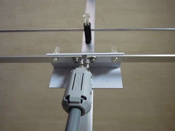
A YBN70-5m for testing BC by Jozef, HA1VQ
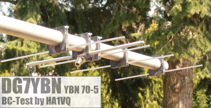
Element insulators are HA1KYY made

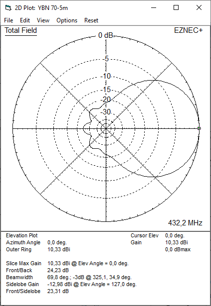
Performance Data
                     ele. 6 mm
Gain vs. isotr. Rad.  10.3 dBi
Gain vs. Dipole        8.2 dBD
-3 dB E-plane         53.4 deg.
-3 dB H-plane         69.8 deg.
F/B                  -24.2 dB
F/R                  -21.9 dB
Impedance           50/200 ohms
Mechan. Length         480 mm
Electr. Length        0.69 λ

Stacking Dist. h-pol.
top-to-bottom         0.61 m
side-by-side          0.77 m
Geometry
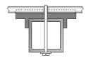 <= 6 mm ele. semi-insulated
mounting on boom, screw upside down with M3 thread in element (as per DJ3JJ, s. Dubus 1/2010)
<= 6 mm ele. semi-insulated
mounting on boom, screw upside down with M3 thread in element (as per DJ3JJ, s. Dubus 1/2010)
               - Plastic Boom & Insulators -     -   Full Free Space   -    - Boom 15x15 mm -    - Boom 20x20 mm -    - Boom 25x25 mm -
        Pos.        1/2 Length   Segm.           1/2 Length  Auto Segm.      Full Lgth +4.8       Full Lgth +7.5      Full Lgth +11.5
                      in NEC                       in NEC

Refl.     0           168.000     11               168.125     10               340.80               343.75               347.50
DE       91           161.500     11               161.625     11               327.80               330.75               334.50
D1      133           155.750     11               155.875      9               316.30               319.25               323.00
D2      266           151.250     10               151.375      9               307.30               310.25               314.00
D3      480           138.500      9               138.625      8               281.80               284.75               288.50
                      ele. 6 mm                    ele. 6 mm                    ele. 6 mm            ele. 6 mm            ele. 6 mm

The Drivers diameter is 10 mm for all examples.
"Ready to saw and drill" data for mounting elements on boom with standard insulators on 20 x 20 mm boom including a 30 mm offset from booms end:
The segmentation used for the plastic boom reference Yagi model is auto segmentation at 500 MHz.
Same was used on longer builds (YU7EF EF7015 +27 Yagis) with good results. Note that the delta length
between Auto Segmentation at 432.1 MHz and 500 MHz is covered by adapting element lengths by 0.25 mm only.
The - Plastic Boom & Insulators - element lengths are what I have published in my article on 432 MHz
On-Boom-BC in Dubus 1/2011. Now why are there two segmentations given? Because for measuring the
set of BC numbers and following real builds we have used the plastic standard insulators throughout.
From first measurment on the plastic boom Yagi to real builds. They made a constant offset which is
handled fitting the NEC models with that little higher segmentation base. See the exellent compliance
between simulation and real plot of the PP-boom Yagi below.
Other diameters and building lengths

               - Plastic Boom & Insulators -     -   Full Free Space   -    - Boom 15x15 mm -    - Boom 20x20 mm -    - Boom 25x25 mm -
        Pos.        1/2 Length   Segm.           1/2 Length  Auto Segm.       Full Length          Full Length          Full Length
                      in NEC                        in NEC

Refl.     0           166.000    11                166.125    10               16x.00               16x.00               16x.00
DE       91           161.500    11                161.625    11               16x.00               16x.00               16x.00
D1      133           153.970    11                154.095     9               16x.00               16x.00               16x.00
D2      266           149.200    10                149.325     9               16x.00               16x.00               16x.00
D3      480           136.100     9                136.225     8               16x.00               16x.00               16x.00
                      ele. 8 mm                    ele. 8 mm                   ele. 8 mm            ele. 8 mm            ele. 8 mm

               - Plastic Boom & Insulators -     -   Full Free Space   -    - Boom 15x15 mm -    - Boom 20x20 mm -    - Boom 25x25 mm -
        Pos.        1/2 Length   Segm.           1/2 Length  Auto Segm.       Full Length          Full Length          Full Length
                      in NEC                       in NEC

Refl.     0           164.700    11                164.820    10               16x.00               16x.00               16x.00
DE       91           161.500    11                161.620    11               16x.00               16x.00               16x.00
D1      133           152.600    11                152.720     9               16x.00               16x.00               16x.00
D2      266           147.300    10                147.420     9               16x.00               16x.00               16x.00
D3      480           134.700     9                134.820     8               16x.00               16x.00               16x.00
                      ele. 10 mm                   ele. 10 mm                  ele. 10 mm           ele. 10 mm           ele. 10 mm

The Drivers diameter is 10 mm for all examples.

• "Ready to saw and drill" data for mounting 4.0 mm elements insulated through boom with SM5BSZ's BC.exe applied
Note that with an elements insulated through boom built for best results boomlength and positions to first /last element must be kept as given.
Because the position of an element relative to its nearer boom end is a serious parameter in the BC.exe.
This table is only valid for:
Boom shape: square
Boom dim: 20 x 20 mm
Wall thickn.: 2.0 mm
Holes in boom: 6.0 mm
Offset rear: 40 mm
Offset front: 40 mm
• Data set for 4 mm elements with rear & front boom end offset = 40 mm

• Data set for 4 mm elements with rear boom end offset = 300 mm for formast mounting
• "Ready to saw and drill" data for mounting 3/16 in (4.76) mm elements insulated through boom with SM5BSZ's BC.exe applied
Note that with an elements insulated through boom built for best results boomlength and positions to first /last element must be kept as given.
Because the position of an element relative to its nearer boom end is a serious parameter in the BC.exe.
This table is only valid for:
Boom shape: square
Boom dim: 20 x 20 mm
Wall thickn.: 2.0 mm
Holes in boom: 7.5 mm
Offset rear: 300 mm
Offset front: 40 mm
• Data set for 3/16 in elements with rear boom end offset = 300 mm for formast mounting
This table is only valid for:
Boom shape: square
Boom dim: 5/8 x 5/8 in
Wall thickn.: 1.6 mm
Holes in boom: 7.5 mm
Offset rear: 300 mm
Offset front: 40 mm
• Data set for 3/16 in elements with rear boom end offset = 300 mm for formast mounting

Pattern and VSWR Plots
Elevation and Azimuth plot at 432.2 MHz

RL and SWR plot with 4nec2
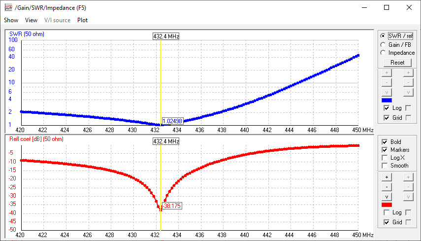
Comparison of simulated and measured Return Loss
Mind that this is on 70 cm Band ... have you seen closer plots of Return Loss by other designers here ever?
There is nothing "trimmed" for best SWR here. The chart shows the PP-boom Yagis without any BC.
This is a measurement "out of the box" with Element lengths trimmed to the 10th of a millimeter
with a large calliper gauge and carefully trimmed and measured symmetrising coax line. This is
yet another confirmation for a low segmentation density close to auto segmetation being much
closer to real world dimensions then often proclamated 30+ segments per wire if it is about a
standard Yagi with a dipole.
Read more about building this Yagi in my Article 'Applied Conversion of Segmented Wires from NEC to 432 MHz Yagi Elements' in Dubus 1/11
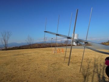
Stacking
here is a proposal how to stack for very high F/B using geometrical shift of the Yagis by 1/4 λ in beam direction.
Stacking distance is 700 mm per Yagi - the whole stack is 5.2 m in height then. This stacking scheme helps to boost
the F/B. It goes back on the S53WW-4, a 4 Yagi stack by Roby, S53WW (http://lea.hamradio.si/~s53ww/s53ww-4/s53ww-4.htm)
The Yagis are fed with individual coax lengths from the splitter on. The geometrical shift must be compensated by longer
coax feed lines. A forward bound shift by a 1/4 λ must be encountered by an extra 1/4 λ added to this Yagis feed line
So that it is acutally fed with a phase lag of -90 degrees. Double that for the next Yagis with 2 x 1/4 λ and same scheme
i.e. 3 x 1/4 λ = -270 deg. for the inner pair of Yagis. Mind the real v-factor of your coax and measure lengths exactly please.

Elevation plot with lowest Yagi at 2.6 m over perfect ground
F/B ratio for this configuration is -38 dB at a HBW of 53.2 deg. and gain of 19.58 dBi in free space

Symmetrising 50 to 50 ohms Feedline to 432 MHz Bent DE
The principle is similar to the 1/4 Lambda coax. Adding 2 x 1/4 Lambda or a half wave line does not change anything but allows
to form a gentle bow below the boom or until behind the Reflector. Follow practical construction hints on "Building a Yagi" page.
 Attenzione!
Take care when lengthening the coax, measure the right length instead of refering to given v-factors only.
Attenzione!
Take care when lengthening the coax, measure the right length instead of refering to given v-factors only.A good choice may be the diam. 5 mm PTFE coax RG-142 B/U: real resonate length (432.2 Mhz as 3/4 Lambda) shield-shield is around 348 mm
 Find more information on Phasing & Matching Lines page
 73, Hartmut, DG7YBN