-
• Main Page
- • Home
• Antennas - • 432 MHz
- YBN 70-5mA 0.5 m 432 MHz blue print of the YBN 2-5m 50 ohms high F/B direct feed 144 MHz Low Noise Yagi
3D Plot

- YBN 70-8zA 1.5 m high gain 28 ohms Yagi.
A design partly based on the hardware of the WY-7010, turning it into a 8 ele. 28 ohms Yagi with cleaner pattern, +1.8 dB gain and better VSWR.
Azimuth Plot
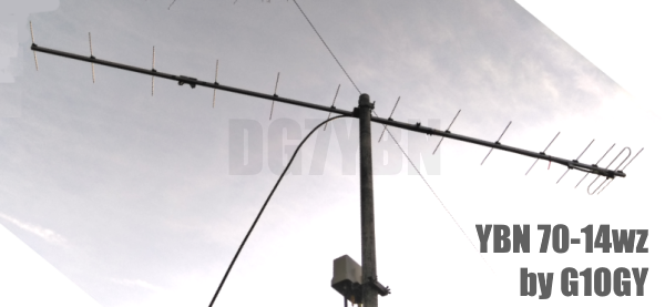
- YBN 70-14wzTune up your 19 ele. Tonna!
A design based on the hardware of the F9FT, turning it into a 14 ele. OWL with cleaner pattern, +0.3 dB gain and SWR less than 1.2 from 430 to 440 MHz
Azimuth Plot
- YBN 70-14+4wA 3.2 m very wideband 50 ohms Yagi with reflector wall that covers the whole 70 cm band with ease
Elevation Plot

- GTV 70-2wA 0.14 m GTV useful for portable operation and up to the satellit band and handheld activities of any kind
Elevation Plot

- GTV 70-3wA 0.21 m GTV useful for portable operation and up to the satellit band and lower noise stacks of any kind
Elevation Plot

- GTV 70-4mA 0.34 m GTV useful for portable operation up to the satellit band and lower noise stacks of any kind
Elevation Plot
- GTV 70-7wA 0.96 m GTV useful for portable operation up to the satellit band and lower noise stacks of any kind
Elevation Plot
- GTV 70-7nA 1.1 m 432 MHz blue print of the low impedance, yet 50 ohms direct feed 144 MHz Low Noise Yagi introduced in Dubus 1/2013
Elevation Plot
- GTV 70-8nA 1.3 m 432 MHz GTV with high gain but low backlobe volume. Makes a very compact 4 Yagi bay for QRP EME or contesting.
Elevation Plot
- GTV 70-9wA 1.44 m GTV ment to be useful as a vertical stack for contesting or be an ideal small size portable Yagi
Elevation Plot

- GTV 70-10wA 1.63 m GTV useful for portable operation up to the satellit band and lower noise stacks of any kind
Elevation Plot
- GTV 70-11wA 2.01 m GTV ment to be useful as a vertical stack for contesting or be an ideal small size portable Yagi or minimum size EME 4 bay
Elevation Plot
- GTV 70-13mA 2.5 m GTV ment to be useful as a vertical stack for contesting or be an ideal small size portable Yagi or minimum size EME 4 bay
Elevation Plot
- GTV 70-14m2.9 m version of the low impedance, yet 50 ohms direct feed Low Noise Yagi with bent DE introduced in Dubus 1/2013
Elevation Plot
- GTV 70-17m3.7 m version of the low impedance, yet 50 ohms direct feed Low Noise Yagi with bent DE introduced in Dubus 1/2013
Elevation Plot

- GTV 70-18w4.0 m version of the low impedance, yet 50 ohms direct feed Low Noise Yagi with bent DE introduced in Dubus 1/2013
Elevation Plot
- GTV 70-19m4.2 m version of the low impedance, yet 50 ohms direct feed Low Noise Yagi with bent DE introduced in Dubus 1/2013
Elevation Plot

- GTV 70-21n4.7 m version of the low impedance, yet 50 ohms direct feed Low Noise Yagi with bent DE introduced in Dubus 1/2013
Elevation Plot

- GTV 70-23m5.3 m version of the low impedance, yet 50 ohms direct feed Low Noise Yagi with bent DE introduced in Dubus 1/2013
Elevation Plot
- GTV 70-25m5.9 m version of the low impedance, yet 50 ohms direct feed Low Noise Yagi with bent DE introduced in Dubus 1/2013
Elevation Plot
- GTV 70-30m7.3 m version of the low impedance, yet 50 ohms direct feed Low Noise Yagi with bent DE introduced in Dubus 1/2013
Elevation Plot
- GTV 70-34w8.5 m version of the low impedance, yet 50 ohms direct feed Low Noise Yagi with bent DE introduced in Dubus 1/2013
Elevation Plot
- GTV 70-46w12.0 m version of the low impedance, yet 50 ohms direct feed Low Noise Yagi with bent DE introduced in Dubus 1/2013
Elevation Plot

- DL6WU YagisThe DL6WU Longyagi Series
Sample plot: 32 el. plus 4 x reflector
Elevation Plot

- YBN 70-5m


A New 432 MHz Tonna?
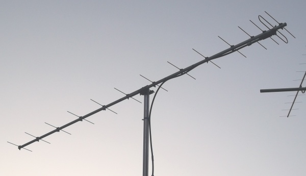
No ... a design based on the 19 ele. Tonna's hardware
Key issue was to recycle as many elements and holes in the boom as possible. So that this is not a
record breaking highest G/T design but something feasible to turn the 19 ele. Tonna into with little effort.
Further a quite reliable design that acts forgiving if we do not meet the new element lengths or positions
up to the 10th mm. Date of issue: Feb. 18th, 2014.
The 19 ele. Tonna has it all:
• It is 12.5 ohms with a tight driver cell, as very up to date designs have it
• It comes with a folded dipole to make it 50 ohms
• It has the well known 'Tonna match' quarter wave sleeve tube
• It is a 12.5 ohms design with fully direct feed
• It is leightweight as can be but has proven to be mechanically robust
The only setback is its pre "double optimised Yagis" design, using fixed distances of 0.25 wl for the elements.
What lies closer at hand than to set up a design based on the nice properties the Tonna provides?
All the mechanical parts of the Tonna can be reused. To rebuild the 19 ele. into this 14 ele. design we need
to drill 9 holes (plus two for a new boom connector), shorten 5 elements and cut one fresh element.
YBN 70-14wz OWA Yagi
A wide band design covering the full 430 ... 440 MHz with an SWR better than 1.2Current distribution
YBN 70-14wz by G1OGY
Performance Data
Gain vs. isotr. Rad.  16.2 dBi (orig. 19 ele. = 15.9 dBi in my simulation)
Gain vs. Dipole       14.0 dBD
-3 dB E-plane         29.8 deg.
-3 dB H-plane         31.7 deg.
F/B                  -22.9 dB
F/R                  -22.4 dB
Impedance               50 ohms
Mechan. Length        2840 mm
Electr. Length        4.02 λ

Stacking Dist. h-pol.
top-to-bottom         1.27 m
side-by-side          1.35 m
Geometry
These are cutting lengths for re-building with Tonna material.
        Ele.Pos.   Hole       Ele. Length   Ele. Notes

ex.Refl.   0       omitted    -             -
Refl.     15       new        343.5         shortened Refl.
DE        68       existing   use original Folded DE
D1       135       existing   320.0         shortened D1
D2       227       existing   312.8         shortened D2 (corr. Jan. 2022)
D3       384       existing   305.0         orig. D3
D4       600       new        302.5         NEW 4mm rod
D5       832       new        301.5         orig. D4
D6      1102       new        297.5         orig. D5
D7      1379       new        293.5         shortened D6
D8      1650       new        291.5         shortened D7
D9      1934       new        290.5         orig. D8
D10     2233       new        285.0         orig. D9
D11     2521       new        285.0         orig. D10
D12     2792       existing   276.0         orig. D14

Ele. Position measures are with original Refl. as zero.

ATTENTION: Due to the form of the plastic clamps the bore
positions are 5 mm behind the ele. positions given!
Pattern and VSWR Plots
Azimuth and Elevation plot at 432.1 MHz
The nec model for this is segmented at 1050 MHz.
Which leads to a stepped segmentation of 25 for the reflector down to 20 for D12
A total BC of 8.45 mm between this model and the real build seems alright.
Elev. Plot with Folded DE with Offset as build
|
Azim. Plot
|
Elev. Plot with Folded DE in ele. plane
|
Elev. Plot is asymmetrical due to using original 'Tonna Antennes' Hardware, a Folded Dipole but elements mounted on 16 x 16 mm boom.
But most of those rear lobes point upwards into the cold sky and add little to the Antenna Temperature as average T_sky is 20 K while T_earth is 350 K.
Return Loss plot - with Planar TR1300/1 Analyser
Plotted range is 420 to 450 MHz : First and last marker show start and end of the 70 cm band.
Achievement - Pattern of original Tonna 19 ele. vs. 14 ele. design - less weight & wind load, more gain & far less lobes towards hot earth:
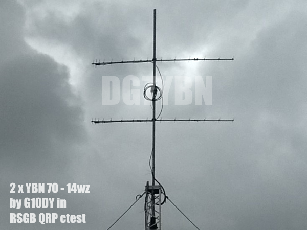
Stacking
Stacking Dist.    DL6WU Formula
top-to-bottom         1.27 m
side-by-side          1.35 m
The typical 4 Yagi Bay with distances per DL6WU

Due to the Folded Dipole in model the Average Gain overshoots by 0.003 or 0.3 percent for the lossless simulation.
To be very correct this is calculated from Average Gain = 1.003 to 1.000 using the KF2YN formulas:
                     YBN design        orig. Tonna
Gain vs. isotr. Rad.  22.1 dBi          21.9 dBi
Gain vs. Dipole       19.9 dBD          19.7 dBD
T_loss                 6.1 K             6.1 K
T_ant                 33.5 K*           39.1 K*
G/T                   6.82 dB*          5.96 dB*      (corrected 2014.02.07)

Theoretical numbers, no phasing line losses
nor imperfections caused by H-frame included
*) T_sky = 20 K, T_earth = 350 K as in VE7BQH G/T table
A vertical stack of 4 Yagis with distances per DL6WU
|
|
Might this be your next contest array? It is leightweight and tolerates a pole through the antenna planes due to the large band width of this design
Gain vs. isotr. Rad.  22.1 dBi
Gain vs. Dipole       19.9 dBD
-3 dB H-plane         30.2 deg.
-3 dB E-plane          6.8 deg.
F/B                  -23.8 dB

Overall Height        3810 mm
Building
Special tools and material that you need for this redesign
• a 4.0 or 4.2 mm drill for the new element holder holes
• a 5.0 or 5.2 mm drill for the new boom connectors holes
• an electric drill
• a metal hand saw
• a tape measure

• a 302.5 mm piece of 4 mm aluminium rod
• a 5/8" boom connector or 100 mm of 5/8" or 20x20x2 mm square tube to make one
• 2 screws M5 x 30 mm, washers and nuts
• insulating tape
• clear tape
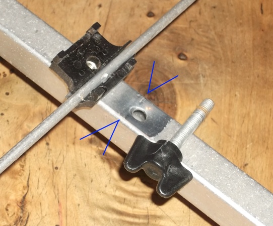
All position measures are related to elements (all incl. reflector) infront of screw, see fig. 1.
|
Fig. 1: How to mark the new bores positions: Bore new relf. pos. (+15 mm) and mount it. Then latch your tape measure there and mark positions acc. table below 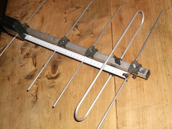
|
Fig. 2: The D7 is so close to the end of the front section of the boom that we need a new connector. A 5/8 inch connector should fit, or we make one by ourselfs, s. fig. 3. 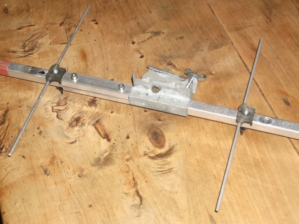
|
Fig. 3: Length is 100 mm, made from a piece of square tube in dim. as above - which is cut into two pieces alongside. Place just in front of plastic holder. Drill holes 15 mm from each end. 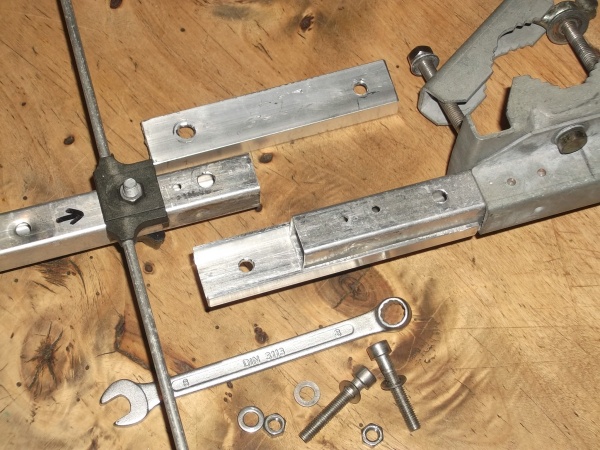
|
How to seal the old holes in boom
Fig. 4: Wrap insulating tape around the hole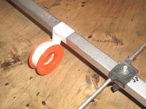
|
Fig. 5: Wrap clear tape on top of the insulating tape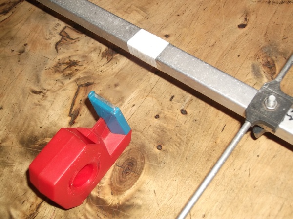
|
Fig. 6: Ready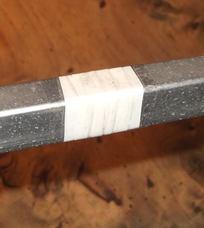
|

| Attenzione!
Bore Positions refer to the tape measure latched to the reflector in NEW position, s. Fig. 1 ... which means that its thickness of 4 mm adds while for all forward bound ele. we subtract 5 mm for the deplacement between screw and ele for these Tonna made ele. holders. |
          Hole Pos.   Notes

ex.Refl.    (-15)     omitted / hole to hole
new Refl. = latching point of tape measure = zero forward bound
DE           49       existing
D1          116       existing
D2          208       existing
D3          365       existing
D4          581       new
D5          813       new
D6         1083       new
D7         1360       new
D8         1631       new
D9         1915       new
D10        2214       new
D11        2502       new
D12        2773       existing

Ele. Position are +4 mm each / Refl. -4 mm due to latching the tape measure to its 'rear'
Does the Tonna have a Contact Problem?
Much has been discussed about how to fasten elements on / through booms. The usual and fully understandable
general meaning is that either "full contact" welded, screwed or achieved by a press fit OR fully insulated
with quality plastic insulators is THE way to go. For top performers this is true. But read on ...
The newer Tonnas use a simple "press element onto boom" with a plastic clamp. As the aluminium ages when
on the mast in all weather we fear that this weak contact will lessen and thus the BC will be shifted
causing the Yagi to shift in its frequency response.
As we can deduce from all the oxide we can see on its surfaces everywhere ... except for underneath the clamps.
The other thing we notice are the grooves the elements have left in the booms surface. Maybe mixed
with marks left by manufacturing tool. However, looking at the plot below this elder exemplar performs
absolutely well. I did not polish anything as preparation, up on the pole and connect to the analyser.
Return Loss Plot of the original F9FT Tonna 19 ele. Yagi
Conclusions
The design is so wide band that I can not say if it moved by some 100 kHz. But it is clear that this maybe 15 years
old Yagi is fully usable with good parameters. As we are talking RF here this might be due to capacitive coupling effects
rather then a good electrical contact. Anyhow is works.
73, Hartmut, DG7YBN