-
• Main Page
- • Home
• Antennas - • 432 MHz
- YBN 70-5mA 0.5 m 432 MHz blue print of the YBN 2-5m 50 ohms high F/B direct feed 144 MHz Low Noise Yagi
3D Plot

- YBN 70-8zA 1.5 m high gain 28 ohms Yagi.
A design partly based on the hardware of the WY-7010, turning it into a 8 ele. 28 ohms Yagi with cleaner pattern, +1.8 dB gain and better VSWR.
Azimuth Plot
- YBN 70-14wzTune up your 19 ele. Tonna!
A design based on the hardware of the F9FT, turning it into a 14 ele. OWL with cleaner pattern, +0.3 dB gain and SWR less than 1.2 from 430 to 440 MHz
Azimuth Plot
- YBN 70-14+4wA 3.2 m very wideband 50 ohms Yagi with reflector wall that covers the whole 70 cm band with ease
Elevation Plot

- GTV 70-2wA 0.14 m GTV useful for portable operation and up to the satellit band and handheld activities of any kind
Elevation Plot

- GTV 70-3wA 0.21 m GTV useful for portable operation and up to the satellit band and lower noise stacks of any kind
Elevation Plot

- GTV 70-4mA 0.34 m GTV useful for portable operation up to the satellit band and lower noise stacks of any kind
Elevation Plot
- GTV 70-7wA 0.96 m GTV useful for portable operation up to the satellit band and lower noise stacks of any kind
Elevation Plot
- GTV 70-7nA 1.1 m 432 MHz blue print of the low impedance, yet 50 ohms direct feed 144 MHz Low Noise Yagi introduced in Dubus 1/2013
Elevation Plot
- GTV 70-8nA 1.3 m 432 MHz GTV with high gain but low backlobe volume. Makes a very compact 4 Yagi bay for QRP EME or contesting.
Elevation Plot
- GTV 70-9wA 1.44 m GTV ment to be useful as a vertical stack for contesting or be an ideal small size portable Yagi
Elevation Plot

- GTV 70-10wA 1.63 m GTV useful for portable operation up to the satellit band and lower noise stacks of any kind
Elevation Plot
- GTV 70-11wA 2.01 m GTV ment to be useful as a vertical stack for contesting or be an ideal small size portable Yagi or minimum size EME 4 bay
Elevation Plot
- GTV 70-13mA 2.5 m GTV ment to be useful as a vertical stack for contesting or be an ideal small size portable Yagi or minimum size EME 4 bay
Elevation Plot
- GTV 70-14m2.9 m version of the low impedance, yet 50 ohms direct feed Low Noise Yagi with bent DE introduced in Dubus 1/2013
Elevation Plot
- GTV 70-17m3.7 m version of the low impedance, yet 50 ohms direct feed Low Noise Yagi with bent DE introduced in Dubus 1/2013
Elevation Plot

- GTV 70-18w4.0 m version of the low impedance, yet 50 ohms direct feed Low Noise Yagi with bent DE introduced in Dubus 1/2013
Elevation Plot
- GTV 70-19m4.2 m version of the low impedance, yet 50 ohms direct feed Low Noise Yagi with bent DE introduced in Dubus 1/2013
Elevation Plot

- GTV 70-21n4.7 m version of the low impedance, yet 50 ohms direct feed Low Noise Yagi with bent DE introduced in Dubus 1/2013
Elevation Plot

- GTV 70-23m5.3 m version of the low impedance, yet 50 ohms direct feed Low Noise Yagi with bent DE introduced in Dubus 1/2013
Elevation Plot
- GTV 70-25m5.9 m version of the low impedance, yet 50 ohms direct feed Low Noise Yagi with bent DE introduced in Dubus 1/2013
Elevation Plot
- GTV 70-30m7.3 m version of the low impedance, yet 50 ohms direct feed Low Noise Yagi with bent DE introduced in Dubus 1/2013
Elevation Plot
- GTV 70-34w8.5 m version of the low impedance, yet 50 ohms direct feed Low Noise Yagi with bent DE introduced in Dubus 1/2013
Elevation Plot
- GTV 70-46w12.0 m version of the low impedance, yet 50 ohms direct feed Low Noise Yagi with bent DE introduced in Dubus 1/2013
Elevation Plot

- DL6WU YagisThe DL6WU Longyagi Series
Sample plot: 32 el. plus 4 x reflector
Elevation Plot

- YBN 70-5m
GTV 70-30m Yagi with bent Driven Element
EME + SSB band Longyagi
This Yagi has very low back lobes for its length. It may serve as single antenna for Tropo or make a nice 4 Yagi EME array.
It also makes a quiet contest antenna due to its high F/B. The bent DE (K6STI style) transforms from approx. 17 ohms to 50 ohms at feed point.
GTV 70-30m buit by I3QJZ

Roberto reports: "... I tested the antenna on the last contests working very good and low noise on receiving, many thanks".
GTV 70-30m used by TD9CHR & TD9FYC Guatemala DX-pedition

Watch the DX-pediton movie on Youtube https://www.youtube.com/watch?v=xnxVaHpQ8_g
GTV 70-30m Rope built by Marek, SP4ELF
Testing with help of Marcin SQ4CUC, Alexander RA2FGG and Romek SP4JCP in -10 C frost produced 2 QSOs in JT65.
Marek:"We have recovered many traces of EME stations but the conditions did not allow for longer work. We had
difficult weather conditions, frost -10 degrees and snowfall, clouds. Despite everything, the antenna worked
very well. Our equipment is FT857 and 200W we did not use LNA for technical reasons." Click for large photo
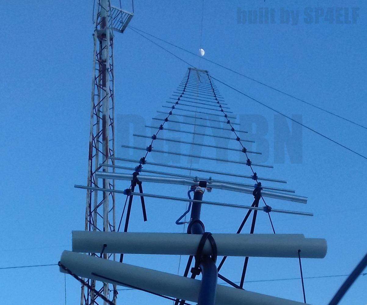
Sub-Website with more info on this rope Yagi


GTV 70-30w Rope built by Thomas, M0ABA at MX0CNS
Look at this: A close to 8 m long GTV 70-30m Rope Yagi built on Kevlar Kite lines,
4 mm elements and a 1/4 λ sleeve with Pawsey symmmetrising ...


There are details and all the news to be posted shortly about this antenna on the MX0CNS facebook
M0ABA at MX0CNS: Screenshot of WSJT of first QSO with the Rope Yagi, beam slightly off the moon still,
60 W at feed at MX0CNS <> DL7APV

GTV 70-30m built by Chris, PA2CHR with 8 mm Elements on Boom, BC acc. DG7YBN


Current distribution


Short Screenshot Movie showing rotating 3D Pattern
To watch the rotating 3D Pattern movie by F5JM click here pse
Performance Data
Specs: with 4 mm elements @ 432.1 MHz
Gain vs. isotr. Rad.  19.7 dBi
Gain vs. Dipole       17.6 dBD
-3 dB E-plane         20.6 deg.
-3 dB H-plane         21.2 deg.
F/B                  -33.8 dB
F/R                  -33.8 dB
Impedance               50 ohms
Mechan. Length        7276 mm
Electr. Length        10.48 λ

Stacking Dist. h-pol.
top-to-bottom         1.89 m
side-by-side          1.94 m
Geometry
Geometry for 4 mm elements


The Drivers diameter is 10 mm for all examples.
Use EZNEC's Auto-Segmentation at 1050 MHz.
A simple symmetrising member may be made from a 3 x 1/4 Lambda line grounded at the far side with
N-flange-bushing and an aluminium plate and ferrite added as close as possible to the DE, see below.
How many OMs have been looking up this design?
Geometry
Geometry for 4 mm elements
"Ready to saw and drill" data for mounting elements through boom with BC according SM5BSZ's BC.exe:
Note: with through Boom BC it is important to stick to the boom end offsets given below!
|
This table is only valid for: Boom shape: square Boom dim: 25 x 25 mm Wall thickn.: 2.0 mm Holes in boom: 6.0 mm Offset rear: 40 mm Offset front: 40 mm |
|

Note: This includes a "Segmentation Density Correction" (SBC) of 1.10 mm plus an offset of 0.70 mm per element = 1.80 mm
for compensation of the insulators (7arrays.com
Note: Other insulators will need other offset, with their length being probably the most important parameter for this.
Thus I advise to cut other plastic insulators to 7 mm each to match at least the length of the pilot insulators.
Note: with through Boom BC it is important to stick to the boom end offsets given below!
Read abt. the SBC here

Using a large calliper gauge to control lenghts to the 10th of a millimeter is a must.
Ø8 mm Elements - On Boom - Dimensions (BC acc. DG7YBN)

Actual BC for on a 25 x 25 mm Boom with standard insulators is 11.0 mm, SBC is 1.37 mm (433.7 - 432.2 MHz),
total length to add is ~ 12.37 mm

Using a large calliper gauge to control lenghts to the 10th of a millimeter is a must.
Sketch of Bent Dipole

Pattern and VSWR Plots
Elevation and Azimuth plot at 432.1 MHz


SWR and Return Loss plots - simulated with 4nec2

GTV 70-30 with Folded Dipole
The straight split bent dipole can be replaced with a bent folded dipole like in any non-bent Yagi design.
In doing so the transformation ratio of 1:4 remains. The bent folded dipole versions impedance is 200 ohms.
The folded dipole itself is of Ø 8 mm; I recommend an 'elements through boom' built.
So that the folded dipole is centered in the element plane for best symmetry in the elevation pattern.
For building with elements on boom see second sketch.
Geometry of the Folded Dipole
In the model we use the center of the tube, regardless of its actual diameter.
For builds ...
• ... with elements mounted through boom (Folded Dipole in element plane) use these dimensions

• ... with 8 mm elements mounted on 25 x 25 mm boom use these dimensions

D1 : Position: 156.5, length 311.5 + 7.5 mm of BC + 1.1 mm of SBC = D1 : 320.1 mm
Downloads
EZNEC file of this Yagi with 4 mm elements
Stacking
As on the 432 MHz Band the Y-factor = T_earth / T_sky is that high I see little chances in
bettering an array's RX performance by using "Over Stacking" distances. However, depending
the level of local QRM it might be worthwhile to try less distance, especially in H-plane.

Stacking Dist.    DL6WU Formula
H-plane               1.89 m
E-plane               1.94 m
Elevation plot and data of 4 Yagi bay using DL6WU stacking distances

TANT screenshot of this Yagi with 4 mm elements

Gain vs. isotr. Rad.  25.54 dBi
Gain vs. Dipole       23.39 dBD
-3 dB H-plane, appr.  -.- deg.
-3 dB E-plane, appr.  -.- deg.
F/B                   -.- dB
F/R                   -.- dB
T_ant                 29.3 K*
G/T                  10.87 dB*
TANT screenshot of this Yagi with 8 mm elements

Gain vs. isotr. Rad.  25.59 dBi
Gain vs. Dipole       23.44 dBD
-3 dB H-plane, appr.  10.0 deg.
-3 dB E-plane, appr.  10.0 deg.
F/B                   33.6 dB
F/R                   32.8 dB
T_ant                 26.0 K*
G/T                  11.43 dB*
Theoretical numbers, no phasing line losses
nor imperfections caused by H-frame included
*) T_sky = 20 K, T_earth = 350 K as in VE7BQH G/T table
Symmetrising 50 to 50 ohms Feedline to 432 MHz Bent DE
The principle is similar to the 1/4 Lambda coax. Adding 2 x 1/4 Lambda or a half wave line does not change anything but allows
to form a gentle bow below the boom or until behind the Reflector. Follow practical construction hints on "Building a Yagi" page.

 Attenzione!
Take care when lengthening the coax, measure the right length instead of refering to given v-factors only.
Attenzione!
Take care when lengthening the coax, measure the right length instead of refering to given v-factors only.A good choice may be the diam. 5 mm PTFE coax RG-142 B/U: real resonate length (432.2 Mhz as 3/4 Lambda) shield-shield is around 348 mm
 Find more information on Phasing & Matching Lines page
 73, Hartmut, DG7YBN