-
• Main Page
- • Home
• Antennas - • 432 MHz
- YBN 70-5mA 0.5 m 432 MHz blue print of the YBN 2-5m 50 ohms high F/B direct feed 144 MHz Low Noise Yagi
3D Plot

- YBN 70-8zA 1.5 m high gain 28 ohms Yagi.
A design partly based on the hardware of the WY-7010, turning it into a 8 ele. 28 ohms Yagi with cleaner pattern, +1.8 dB gain and better VSWR.
Azimuth Plot
- YBN 70-14wzTune up your 19 ele. Tonna!
A design based on the hardware of the F9FT, turning it into a 14 ele. OWL with cleaner pattern, +0.3 dB gain and SWR less than 1.2 from 430 to 440 MHz
Azimuth Plot
- YBN 70-14+4wA 3.2 m very wideband 50 ohms Yagi with reflector wall that covers the whole 70 cm band with ease
Elevation Plot

- GTV 70-2wA 0.14 m GTV useful for portable operation and up to the satellit band and handheld activities of any kind
Elevation Plot

- GTV 70-3wA 0.21 m GTV useful for portable operation and up to the satellit band and lower noise stacks of any kind
Elevation Plot

- GTV 70-4wA 0.33 m wideband GTV useful for portable operation up to the satellit band and lower noise stacks of any kind
Elevation Plot
- GTV 70-4mA 0.34 m GTV useful for portable operation up to the satellit band and lower noise stacks of any kind
Elevation Plot
- GTV 70-7wA 0.96 m GTV useful for portable operation up to the satellit band and lower noise stacks of any kind
Elevation Plot
- GTV 70-7nA 1.1 m 432 MHz blue print of the low impedance, yet 50 ohms direct feed 144 MHz Low Noise Yagi introduced in Dubus 1/2013
Elevation Plot
- GTV 70-8nA 1.3 m 432 MHz GTV with high gain but low backlobe volume. Makes a very compact 4 Yagi bay for QRP EME or contesting.
Elevation Plot
- GTV 70-9wA 1.44 m GTV ment to be useful as a vertical stack for contesting or be an ideal small size portable Yagi
Elevation Plot

- GTV 70-10wA 1.63 m GTV useful for portable operation up to the satellit band and lower noise stacks of any kind
Elevation Plot
- GTV 70-11wA 2.01 m GTV ment to be useful as a vertical stack for contesting or be an ideal small size portable Yagi or minimum size EME 4 bay
Elevation Plot
- GTV 70-13mA 2.5 m GTV ment to be useful as a vertical stack for contesting or be an ideal small size portable Yagi or minimum size EME 4 bay
Elevation Plot
- GTV 70-14m2.9 m version of the low impedance, yet 50 ohms direct feed Low Noise Yagi with bent DE introduced in Dubus 1/2013
Elevation Plot
- GTV 70-17m3.7 m version of the low impedance, yet 50 ohms direct feed Low Noise Yagi with bent DE introduced in Dubus 1/2013
Elevation Plot

- GTV 70-18w4.0 m version of the low impedance, yet 50 ohms direct feed Low Noise Yagi with bent DE introduced in Dubus 1/2013
Elevation Plot
- GTV 70-19m4.2 m version of the low impedance, yet 50 ohms direct feed Low Noise Yagi with bent DE introduced in Dubus 1/2013
Elevation Plot

- GTV 70-21n4.7 m version of the low impedance, yet 50 ohms direct feed Low Noise Yagi with bent DE introduced in Dubus 1/2013
Elevation Plot

- GTV 70-23m5.3 m version of the low impedance, yet 50 ohms direct feed Low Noise Yagi with bent DE introduced in Dubus 1/2013
Elevation Plot
- GTV 70-25m5.9 m version of the low impedance, yet 50 ohms direct feed Low Noise Yagi with bent DE introduced in Dubus 1/2013
Elevation Plot
- GTV 70-30m7.3 m version of the low impedance, yet 50 ohms direct feed Low Noise Yagi with bent DE introduced in Dubus 1/2013
Elevation Plot
- GTV 70-34w8.5 m version of the low impedance, yet 50 ohms direct feed Low Noise Yagi with bent DE introduced in Dubus 1/2013
Elevation Plot
- GTV 70-46w12.0 m version of the low impedance, yet 50 ohms direct feed Low Noise Yagi with bent DE introduced in Dubus 1/2013
Elevation Plot

- DL6WU YagisThe DL6WU Longyagi Series
Sample plot: 32 el. plus 4 x reflector
Elevation Plot

- YBN 70-5m
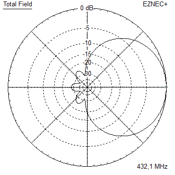
GTV 70-7w Yagi with bent Driven Element
Wideband version ... 430 to 438 (440) MHz
This Yagi has very low back lobes for its length and bandwidth.
Simulated Return Loss (S11) is better -30 dB from 430 to 438 MHz. It may serve as single antenna for portable
use and is easy to repoduce. It certainly makes a useful 4 x vertical stack. It makes a quiet contest antenna due to its
high F/B. The bent DE (K6STI style) transforms from approx. 17 ohms to 50 ohms at feed point. Design date: May 2019.
This designs origin is the YBN 3+7 SAT handheld combination Yagi.
With M0ABA having built it the first thing he did was a moon bounce test,
which went well with only 60 W at the feedpoint.
See building details and screenshots of the EME QSO on the SAT Yagis website
GTV70-7w portable version built by Thomas, M0ABA
This Yagi is built on a boom 5/8 inch with elements 4.0 mm held in place with insulators by 7arrays

GTV70-7w built by Thomas, M0ABA

GTV70-7w built by Wolf, DF7KB
This Yagi is built on a boom 25 x 25 x 2 mm with elements 4.0 mm held in place with insulators by 7arrays


Current distribution

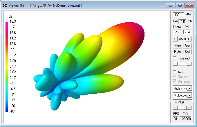
3D Pattern (432.1 MHz)
Performance Data
Specs: with 6.35 mm elements @ 432.1 MHz
Gain vs. isotr. Rad.  12.3 dBi
Gain vs. Dipole       10.1 dBD
-3 dB E-plane         44.3 deg.
-3 dB H-plane         52.2 deg.
F/B                  -26.5 dB
F/R                  -21.5 dB
Impedance               50 ohms
Mechan. Length         960 mm incl. 2 x 30 mm stand off
Electr. Length        1.30 λ

Stacking dist. h-pol.
top-to-bottom         0.79 m or 2.59 ft
side-by-side          0.92 m or 3.02 ft
How many OMs have been looking up this design?
Geometry

Table 1: 70 cm section, 6.35 mm elements through a 5/8 inch boom,
formast mount with 280 mm offset on rear boom end:
"Ready to saw and drill" data for mounting elements through boom with BC according SM5BSZ's BC.exe:
|
This table is only valid for: Boom shape: square Boom dim: 5/8 x 5/8 inch Wall thickn.: 1/6 inch = 1.6 mm Holes in boom: 8.0 mm Offset rear: 280 mm Offset front: 30 mm |
|
Note: This does include an SBC of 1.74 mm plus a correction for the insulators (v-factor!) of 0.7 mm = 2.44 mm
Note: with through Boom BC it is important to stick to the boom end offsets given below!

Table 1: 70 cm section, 4.00 mm elements through a 20 x 20 mm boom,
formast mount with 280 mm offset on rear boom end:
"Ready to saw and drill" data for mounting elements through boom with BC according SM5BSZ's BC.exe:
|
This table is only valid for: Boom shape: square Boom dim: 20 x 20 mm Wall thickn.: 2.0 mm Holes in boom: 6.0 mm Offset rear: 280 mm Offset front: 40 mm |
|
Note: This does include an SBC of 1.74 mm plus a correction for the insulators (v-factor!) of 0.7 mm = 2.44 mm
Note: with through Boom BC it is important to stick to the boom end offsets given below!

Table 1: 70 cm section, 4.00 mm elements through a 5/8 inch boom,
formast mount with 280 mm offset on rear boom end:
"Ready to saw and drill" data for mounting elements through boom with BC according SM5BSZ's BC.exe:
|
This table is only valid for: Boom shape: square Boom dim: 5/8 x 5/8 inch Wall thickn.: 1/6 inch = 1.6 mm Holes in boom: 6.0 mm Offset rear: 280 mm Offset front: 40 mm |
|
Note: This does include an SBC of 1.74 mm plus a correction for the insulators (v-factor!) of 0.7 mm = 2.44 mm
Note: with through Boom BC it is important to stick to the boom end offsets given below!
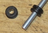
For making of a 'Blade Dipole'
Sketch of Bent Dipole

Radiation Pattern and VSWR Plots
Elevation and Azimuth plot at 432.1 MHz (6.35 mm ele.)


SWR and Return Loss plots - simulated with 4nec2

M0ABA plotted Return Loss 70 cm: -44 dB at 435.5 MHz

Elevation Pattern 430 - 438 MHz


xpol Details

Offset between h and v-plane is 270 mm
xpol Table 1: 70 cm section, 4.00 mm elements through a 15 x 15 mm boom,
formast mount with 340 mm offset on rear boom end:
"Ready to saw and drill" data for mounting elements through boom with BC according SM5BSZ's BC.exe:
|
This table is only valid for: Boom shape: square Boom dim: 15 x 15 mm Wall thickn.: 2.0mm Holes in boom: 6.0 mm Offset h-plane rear: 340 mm Offset h-plane front: 310 mm Offset v-plane rear: 610 mm Offset v-plane front: 40 mm |
|

Note: This does include an SBC of 1.281.74 mm plus a correction for the insulators (v-factor!) of 0.7 mm
for compensation of the insulators (7arrays.com
Note: with through Boom BC it is important to stick to the boom end offsets given below!

Downloads
none so far
Stacking
Stacking Dist.    DL6WU Formula
H-plane               0.79 m
E-plane               0.96 m
A 4 Yagi bay
Elev. and Az. Plot @ 432.3 MHz


Data for elements 6.35 mm @ 432.3 MHz
Gain vs. isotr. Rad.  18.25 dBi
Gain vs. Dipole       16.10 dBD
-3 dB H-plane, appr.  19.8 deg.
-3 dB E-plane, appr.  23.2 deg.
F/B                  -29.4 dB
F/R                  -23.9 dB
T_ant                140.1 K*
G/T                  -3.21 dB*
Theoretical numbers, no phasing line losses
nor imperfections caused by mast included
*) T_sky = 27 K, T_earth = 1800 K as in newer VE7BQH G/T table
3D pattern plot with 4nec2's 3D viewer

4 x vertical Stack at 770 mm each


8 x vertical Stack at 770 mm each

Symmetrising 50 to 50 ohms feedline to 432 MHz Bent DE
The principle is similar to the 1/4 Lambda coax. Adding 2 x 1/4 Lambda or a half wave line does not change anything but allows
to form a gentle bow below the boom or until behind the Reflector. Follow practical construction hints on "Building a Yagi" page.


 Attenzione!
Take care when lengthening the coax, measure the actual electrical length instead of considering v-factors specified in a catalogue only.
Attenzione!
Take care when lengthening the coax, measure the actual electrical length instead of considering v-factors specified in a catalogue only.A good choice may be the diam. 5 mm PTFE coax RG-142 B/U: real resonate length (432.2 MHz as 3/4 Lambda) shield-shield is around 348 mm
 Find more information on Phasing & Matching Lines page
 73, Hartmut, DG7YBN