-
• Main Page
- • Home
• Antennas - • 432 MHz
- YBN 70-5mA 0.5 m 432 MHz blue print of the YBN 2-5m 50 ohms high F/B direct feed 144 MHz Low Noise Yagi
3D Plot

- YBN 70-8zA 1.5 m high gain 28 ohms Yagi.
A design partly based on the hardware of the WY-7010, turning it into a 8 ele. 28 ohms Yagi with cleaner pattern, +1.8 dB gain and better VSWR.
Azimuth Plot
- YBN 70-14wzTune up your 19 ele. Tonna!
A design based on the hardware of the F9FT, turning it into a 14 ele. OWL with cleaner pattern, +0.3 dB gain and SWR less than 1.2 from 430 to 440 MHz
Azimuth Plot
- YBN 70-14+4wA 3.2 m very wideband 50 ohms Yagi with reflector wall that covers the whole 70 cm band with ease
Elevation Plot

- GTV 70-2wA 0.14 m GTV useful for portable operation and up to the satellit band and handheld activities of any kind
Elevation Plot

- GTV 70-3wA 0.21 m GTV useful for portable operation and up to the satellit band and lower noise stacks of any kind
Elevation Plot

- GTV 70-4mA 0.34 m GTV useful for portable operation up to the satellit band and lower noise stacks of any kind
Elevation Plot
- GTV 70-7wA 0.96 m GTV useful for portable operation up to the satellit band and lower noise stacks of any kind
Elevation Plot
- GTV 70-7nA 1.1 m 432 MHz blue print of the low impedance, yet 50 ohms direct feed 144 MHz Low Noise Yagi introduced in Dubus 1/2013
Elevation Plot
- GTV 70-8nA 1.3 m 432 MHz GTV with high gain but low backlobe volume. Makes a very compact 4 Yagi bay for QRP EME or contesting.
Elevation Plot
- GTV 70-9wA 1.44 m GTV ment to be useful as a vertical stack for contesting or be an ideal small size portable Yagi
Elevation Plot

- GTV 70-10wA 1.63 m GTV useful for portable operation up to the satellit band and lower noise stacks of any kind
Elevation Plot
- GTV 70-11wA 2.01 m GTV ment to be useful as a vertical stack for contesting or be an ideal small size portable Yagi or minimum size EME 4 bay
Elevation Plot
- GTV 70-13mA 2.5 m GTV ment to be useful as a vertical stack for contesting or be an ideal small size portable Yagi or minimum size EME 4 bay
Elevation Plot
- GTV 70-14m2.9 m version of the low impedance, yet 50 ohms direct feed Low Noise Yagi with bent DE introduced in Dubus 1/2013
Elevation Plot
- GTV 70-17m3.7 m version of the low impedance, yet 50 ohms direct feed Low Noise Yagi with bent DE introduced in Dubus 1/2013
Elevation Plot

- GTV 70-18w4.0 m version of the low impedance, yet 50 ohms direct feed Low Noise Yagi with bent DE introduced in Dubus 1/2013
Elevation Plot
- GTV 70-19m4.2 m version of the low impedance, yet 50 ohms direct feed Low Noise Yagi with bent DE introduced in Dubus 1/2013
Elevation Plot

- GTV 70-21n4.7 m version of the low impedance, yet 50 ohms direct feed Low Noise Yagi with bent DE introduced in Dubus 1/2013
Elevation Plot

- GTV 70-23m5.3 m version of the low impedance, yet 50 ohms direct feed Low Noise Yagi with bent DE introduced in Dubus 1/2013
Elevation Plot
- GTV 70-25m5.9 m version of the low impedance, yet 50 ohms direct feed Low Noise Yagi with bent DE introduced in Dubus 1/2013
Elevation Plot
- GTV 70-30m7.3 m version of the low impedance, yet 50 ohms direct feed Low Noise Yagi with bent DE introduced in Dubus 1/2013
Elevation Plot
- GTV 70-34w8.5 m version of the low impedance, yet 50 ohms direct feed Low Noise Yagi with bent DE introduced in Dubus 1/2013
Elevation Plot
- GTV 70-46w12.0 m version of the low impedance, yet 50 ohms direct feed Low Noise Yagi with bent DE introduced in Dubus 1/2013
Elevation Plot

- DL6WU YagisThe DL6WU Longyagi Series
Sample plot: 32 el. plus 4 x reflector
Elevation Plot

- YBN 70-5m
GTV 70-23m Yagi with bent Driven Element
EME + SSB band, with some loss usable for FM up to 435 MHz
This Yagi has very low back lobes for its length. It may serve as single antenna for Tropo or make a nice 4 Yagi EME array.
It also makes a quiet contest antenna due to its high F/B. The bent DE (K6STI style) transforms from approx. 17 ohms to 50 ohms at feed point.
Date of issue of design: 2013.03.11
Current distribution
2015-04-17: Nice photo of a
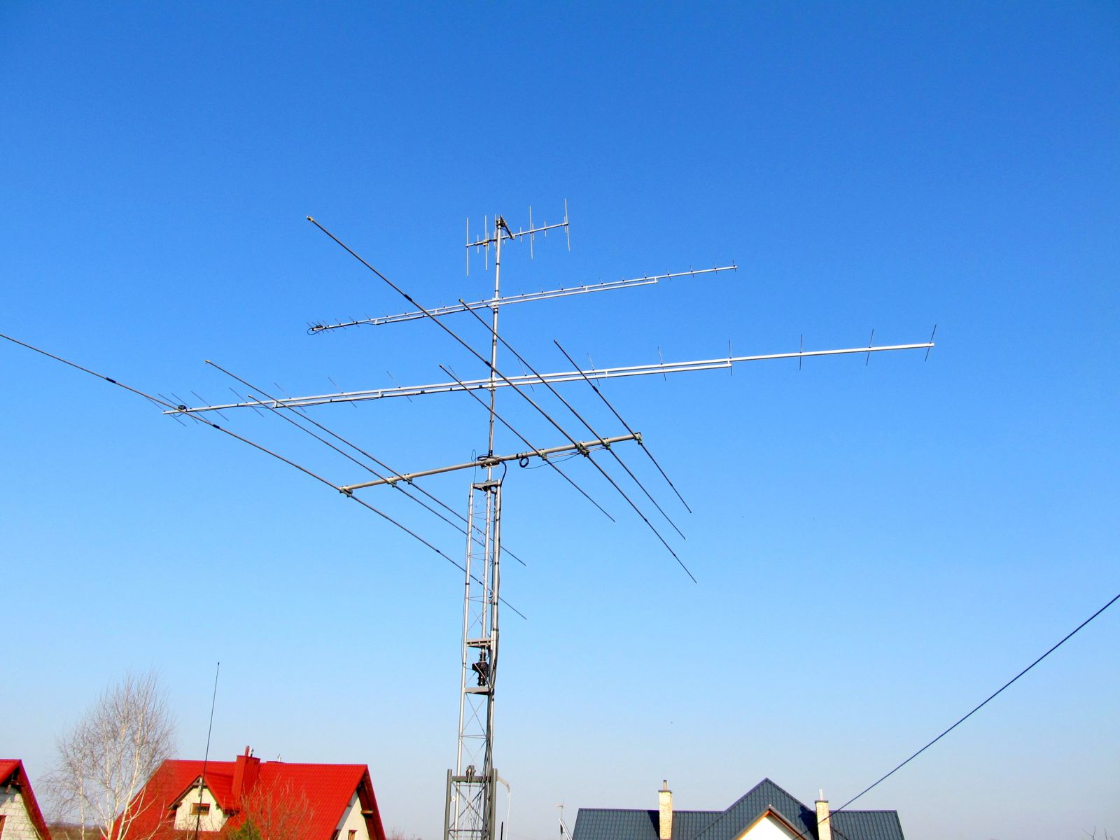 GTV 70-23 m over GTV 2-16w at SP8MRD on qrz.com
GTV 70-23m built by Hannes, OE5JFL


Hannes managed to detect Pulsar B0329-54 on this single Longyagi!
For this he recalculated the design to 430 MHz and built it on a wooden lace and stand.Photo & Image: on courtesy of Hannes, OE5JFL
Read more about this great acheivement on Hannes website
GTV 70-23m built using 8 mm elements on 20 x 20 mm boom by John, G4ZTR

Dipole details: center piece from PTFE, machined on a turning lathe by G4ZTR

VSWR Plot by G4ZTR

Photo and plot on courtesy of G4ZTR, tnx John
GTV 70-23m built on single rope by Dennis, W5RZ
2017-08-20: Battery run EME Station QSO W5RZ - NC1I with ~ 1.2 kW EIRP only
Dennis, W5RZ: "The equipment was a Yaesu FT-817, Tokyo High power amplifier,Signalink USB, and Bioenno 12 AH LiFeP04 battery. Output was 20 watts. ...
The entire station weighs less than 20 pounds, including the rig, battery,
antenna, picnic blanket, etc."
He used a lightweight coax (foam RG8X) from PA to the GTV 70-23m's dipole.


Which might cost 1 ... 2 dB. Nevertheless a QSO was completed. Which also attests
the GTV 70-23m with 'Blade Dipole' to be a forgiving design.
Signal were -25 dB at NC1I / -25 dB at W5RZ
Frank, NC1I on HB9Q logger a few minutes after the QSO:
"Dennis that may be my most amazing 432 EME QSO in my 35 years of activity!"


Tnx to Frank, NC1I for operating his Superstation for this as well.
NC1I 432MHz EME array, Photo on courtesy of Frank, NC1I, click to enlarge
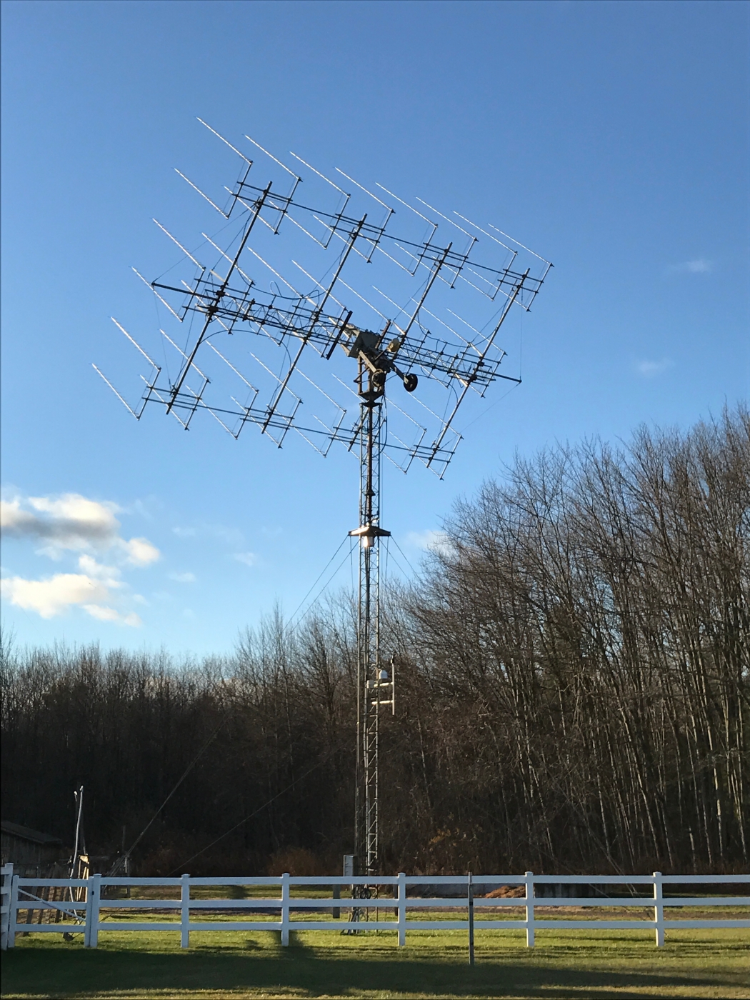
7 meters high, and 3 meters deep (boom length). Gain is around 31.5 dBi and the antennas are K1FO design.
Link to panorama view and more photos on Franks array on GigaPan.com
GTV 70-23m built on 20 x 20 mm boom by Rickus, ZS4A
Following the building samples given on my web closely he reports a VSWR of 1.2 mid band without any tuning done.
Note the boom to mast mounting plate as described here

Performance Data
Gain vs. isotr. Rad.  18.7 dBi
Gain vs. Dipole       16.5 dBD
-3 dB E-plane         23.0 deg.
-3 dB H-plane         23.6 deg.
F/B                  -34.9 dB
F/R                  -32.3 dB
Impedance               50 ohms
Mechan. Length        5240 mm
Electr. Length        7.55 λ

Stacking Dist. h-pol.
top-to-bottom         1.70 m
side-by-side          1.76 m
Geometry
Geometry with 8 mm elements without any BC in EZNEC Wire Editor

The Drivers diameter is 10 mm for all examples. Use EZNEC's Auto-Segmentation at 1050 MHz.
A simple symmetrising member may be made from a 3 x 1/4 Lambda line grounded at the far side with
N-flange-bushing and an aluminium plate and ferrite added as close as possible to the DE, see below.
Building Tables

Ø 8.0 mm Elements - Semi-Insulated on Boom - Dimensions (BC acc. DG7YBN)
"Ready to saw and drill" data for mounting elements on boom with standard insulators on 20 x 20 mm boom including a 30 mm offset from booms end:
Table revised 2018.09.13

 Thin elements insulated through boom
Ø 3/16 inch (4.763 mm) Elements - Insulated through Boom - Dimensions (BC acc. SM5BSZ's BC.exe)
"Ready to saw and drill" data for mounting elements through boom with BC according SM5BSZ's BC.exe:
Note: with through Boom BC it is important to stick to the boom end offsets given below!
This table is only valid for:
Boom shape: square
Boom dim: 20 x 20 mm
Wall thickn.: 1.5 mm
Holes in boom: 7.5 mm
Offset rear: 40 mm
Offset front: 40 mm
Note: This does include a "Segmentation Density Correction" (SBC) of 1.98 mm.
Which does include a correction for the insulators, which is 0.7 mm as a fix offset.
Read abt. the SBC here

Thin elements insulated through boom
Ø 4.0 mm Elements - Insulated through Boom - Dimensions (BC acc. SM5BSZ's BC.exe)
"Ready to saw and drill" data for mounting elements through boom with BC according SM5BSZ's BC.exe:
|
This table is only valid for: Boom shape: square Boom dim: 20 x 20 mm Wall thickn.: 1.5 mm Holes in boom: 6.0 mm Offset rear: 40 mm Offset front: 40 mm |
|

Note: This does include an SBC of 1.98 mm plus a correction of 0.7 mm
for compensation of the insulators (7arrays.com

Using a large calliper gauge to control lenghts to the 10th of a millimeter is a must.
Sketch of Bent Dipole

Pattern and VSWR Plots
Elevation and Azimuth plot at 432.1 MHz


SWR and Return Loss plots - simulated with 4nec2

Downloads
EZNEC file of this Yagi with 4 mm elem.
EZNEC file of this Yagi with 8 mm elem.
Stacking
As on the 432 MHz Band the Y-factor = T_earth / T_sky is that high I see little chances in
bettering an array's RX performance by using "Over Stacking" distances. However, depending
the level of local QRM it might be worthwhile to try less distance, especially in H-plane.

Stacking Dist.    DL6WU Formula
H-plane               1.70 m
E-plane               1.76 m
Elevation plot and data of 4 Yagi bay using DL6WU stacking distances

Gain vs. isotr. Rad.  24.51 dBi
Gain vs. Dipole       22.36dBD
-3 dB H-plane, appr.  10.2 deg.
-3 dB E-plane, appr.  10.5 deg.
F/B                  -32.6 dB
F/R                  -32.3 dB
T_ant                 27.8 K*
G/T                  10.08 dB*
Theoretical numbers, no phasing line losses
nor imperfections caused by H-frame included
*) T_sky = 20 K, T_earth = 350 K as in VE7BQH G/T table
Symmetrising 50 to 50 ohms Feedline to 432 MHz Bent DE
The principle is similar to the 1/4 Lambda coax. Adding 2 x 1/4 Lambda or a half wave line does not change anything but allows
to form a gentle bow below the boom or until behind the Reflector. Follow practical construction hints on "Building a Yagi" page.

 Attenzione!
Take care when lengthening the coax, measure the right length instead of refering to given v-factors only.
Attenzione!
Take care when lengthening the coax, measure the right length instead of refering to given v-factors only.A good choice may be the diam. 5 mm PTFE coax RG-142 B/U: real resonate length (432.2 Mhz as 3/4 Lambda) shield-shield is around 348 mm
 Find more information on Phasing & Matching Lines page
 73, Hartmut, DG7YBN