-
• Main Page
- • Home
• Antennas - • 432 MHz
- YBN 70-5mA 0.5 m 432 MHz blue print of the YBN 2-5m 50 ohms high F/B direct feed 144 MHz Low Noise Yagi
3D Plot

- YBN 70-8zA 1.5 m high gain 28 ohms Yagi.
A design partly based on the hardware of the WY-7010, turning it into a 8 ele. 28 ohms Yagi with cleaner pattern, +1.8 dB gain and better VSWR.
Azimuth Plot
- YBN 70-14wzTune up your 19 ele. Tonna!
A design based on the hardware of the F9FT, turning it into a 14 ele. OWL with cleaner pattern, +0.3 dB gain and SWR less than 1.2 from 430 to 440 MHz
Azimuth Plot
- YBN 70-14+4wA 3.2 m very wideband 50 ohms Yagi with reflector wall that covers the whole 70 cm band with ease
Elevation Plot

- GTV 70-2wA 0.14 m GTV useful for portable operation and up to the satellit band and handheld activities of any kind
Elevation Plot

- GTV 70-3wA 0.21 m GTV useful for portable operation and up to the satellit band and lower noise stacks of any kind
Elevation Plot

- GTV 70-4mA 0.34 m GTV useful for portable operation up to the satellit band and lower noise stacks of any kind
Elevation Plot
- GTV 70-7wA 0.96 m GTV useful for portable operation up to the satellit band and lower noise stacks of any kind
Elevation Plot
- GTV 70-7nA 1.1 m 432 MHz blue print of the low impedance, yet 50 ohms direct feed 144 MHz Low Noise Yagi introduced in Dubus 1/2013
Elevation Plot
- GTV 70-8nA 1.3 m 432 MHz GTV with high gain but low backlobe volume. Makes a very compact 4 Yagi bay for QRP EME or contesting.
Elevation Plot
- GTV 70-9wA 1.44 m GTV ment to be useful as a vertical stack for contesting or be an ideal small size portable Yagi
Elevation Plot

- GTV 70-10wA 1.63 m GTV useful for portable operation up to the satellit band and lower noise stacks of any kind
Elevation Plot
- GTV 70-11wA 2.01 m GTV ment to be useful as a vertical stack for contesting or be an ideal small size portable Yagi or minimum size EME 4 bay
Elevation Plot
- GTV 70-13mA 2.5 m GTV ment to be useful as a vertical stack for contesting or be an ideal small size portable Yagi or minimum size EME 4 bay
Elevation Plot
- GTV 70-14m2.9 m version of the low impedance, yet 50 ohms direct feed Low Noise Yagi with bent DE introduced in Dubus 1/2013
Elevation Plot
- GTV 70-17m3.7 m version of the low impedance, yet 50 ohms direct feed Low Noise Yagi with bent DE introduced in Dubus 1/2013
Elevation Plot

- GTV 70-18w4.0 m version of the low impedance, yet 50 ohms direct feed Low Noise Yagi with bent DE introduced in Dubus 1/2013
Elevation Plot
- GTV 70-19m4.2 m version of the low impedance, yet 50 ohms direct feed Low Noise Yagi with bent DE introduced in Dubus 1/2013
Elevation Plot

- GTV 70-21n4.7 m version of the low impedance, yet 50 ohms direct feed Low Noise Yagi with bent DE introduced in Dubus 1/2013
Elevation Plot

- GTV 70-23m5.3 m version of the low impedance, yet 50 ohms direct feed Low Noise Yagi with bent DE introduced in Dubus 1/2013
Elevation Plot
- GTV 70-25m5.9 m version of the low impedance, yet 50 ohms direct feed Low Noise Yagi with bent DE introduced in Dubus 1/2013
Elevation Plot
- GTV 70-30m7.3 m version of the low impedance, yet 50 ohms direct feed Low Noise Yagi with bent DE introduced in Dubus 1/2013
Elevation Plot
- GTV 70-34w8.5 m version of the low impedance, yet 50 ohms direct feed Low Noise Yagi with bent DE introduced in Dubus 1/2013
Elevation Plot
- GTV 70-46w12.0 m version of the low impedance, yet 50 ohms direct feed Low Noise Yagi with bent DE introduced in Dubus 1/2013
Elevation Plot

- DL6WU YagisThe DL6WU Longyagi Series
Sample plot: 32 el. plus 4 x reflector
Elevation Plot

- YBN 70-5m
YBN 70-8z Yagi 28 ohms Yagi with Straight Dipole
430 - 436 MHz High Gain Yagi
This design has been developed for modifying the WiMo WY-7010 70 cm Yagi.
Design specs are high gain and decent bandwidth while producing a cleaner pattern
than the WY-7010.
The whole story of designing and developing a building scheme and making 20 of these
Yagis is captured in a story written by Vlada, OK1VPZ.
Here: English Version Czech version
Yagis is captured in a story written by Vlada, OK1VPZ.
Here: English Version
Here we go: July 2020 ctest, first outing of the YBN 70-8z at OK2A

1 x 4 x YBN 70-8z vertical stack
1 x 16 x DK7ZB 5 ele. vertical stack
1 x m2 38 ele.
From OK1DIXs report about 70 cm band for this ctest:
"Since OK1VPZ produced 4 new antennas more, we could still build one small stack on a low mast to the north,
where there are no nearby terrain obstacles. This stack also worked better than expected, and the OZ7IGY beacon
could be heard on it."

These Yagis are built on a 15 x 15 mm boom. Dipole box is a SCAME 855 box made in Italy.
See futher details down below in section 'Matching'
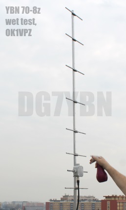
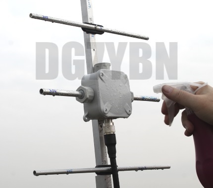
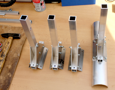
Photo Credit and Yagi Builds: on courtesy of Vlada, OK1VPZ
Current distribution

Performance Data
Specs: with 8 mm elements @ 432.1 MHz
Gain vs. isotr. Rad.  13.9 dBi
Gain vs. Dipole       11.8 dBD
-3 dB E-plane         36.8 deg.
-3 dB H-plane         40.5 deg.
F/B                  -24.0 dB
F/R                  -20.5 dB
Impedance               28 ohms
Mechan. Length      1505.5 mm incl. 2 x 40 mm stand off
Electr. Length        2.05 λ

Stacking dist. h-pol. per DL6WU
top-to-bottom         1.00 m or 3.29 ft (recommended: 0.90 m)
side-by-side          1.10 m or 3.61 ft
How many OMs have been looking up this design?
Geometry
Ø8 mm Elements - On Boom - Dimensions (BC acc. DG7YBN)
"Ready to saw and drill" data for mounting elements on boom with BC according DG7YBN for standard insulators as sold by WiMo, Tinos Funkshop, HF-Kits NL, 7arrays
This Yagi with 8 mm elements on a 15 x 15 mm boom with standard insulators

|
Ele. 8.0 mm DE 10 mm Boom 15 x 15 mm Rear Boom End Offset: 0 mm Front Boom End Offset: 0 mm ... to be added in this table (25 .. 30 mm will do). |

Note: With elements mounted on boom basically any rear and front offset can be used without any modifcation of element lengths.
This Yagi with 8 mm elements on a 20 x 20 mm boom with standard insulators
|
|
Ele. 8.0 mm DE 10 mm Boom 20 x 20 mm Rear Boom End Offset: 350 mm Front Boom End Offset: 30 mm |
Note: With elements mounted on boom basically any rear and front offset can
be used without any modifcation of element lengths. 350 mm rear offset for
formast mounting is a fine distance for a 70 cm Yagi, but you may vary these to
your needs. Mind that below approx. 300 mm interaction with the pole and mast clamp
are very likely.
Radiation Pattern and VSWR Plots
Elevation and Azimuth plot at 432.1 MHz (4 mm ele.)

Comparsion WY-7010 and YBN 70-8z
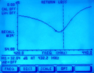
SWR and Return Loss plots - simulated with 4nec2
(I have settled the best Retrun Loss a bit higher for giving headroom in wet weather)
Typical Return Loss, average for the 20 Yagis built by OK1VPZ
| Return Loss, dry Yagi | Return Loss, wet Yagi | |

|
|
Achievable Return Loss, one of best of the 20 Yagis built by OK1VPZ
| Return Loss, dry Yagi | Return Loss, wet Yagi | |

|

|
Gain, F/B and F/R 430 to 440 MHz
Downloads
None so far.
Stacking
As on 432 MHz the Y-factor = T_earth / T_sky is so high, I see little chances to
improve an array's RX performance by using "Over Stacking" distances. However, depending on
the level of local QRM it might be worthwhile to try a decreased distance, especially in the H-plane.
Stacking Dist.    DL6WU Formula
H-plane               1.04 m
E-plane               0.93 m
A 2 Yagi vertical stack

Elev. Plot

A 4 Yagi bay
Elevation and Azimuth Plot
A 4 Yagi vertical stack

Elevation and Azimuth Plot


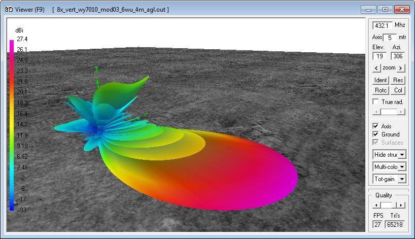
An 8 Yagi vertical stack

Elevation and Azimuth Plot
At 4 m AGL over 'Perfect Ground':

Contest Stacks with increased F/B:
Stagger Stacked 8 x vertical YBN 70-8z
Free Space pattern
Raidiation pattern over 'Perfect Ground', lowest Yagi 4.0 m agl:

Antenna View and Geometry (vertical stacking distance is 930 mm each plane)

Source Phases, feedlines must be -90 deg = 1/4 wl longer etc.

The Yagis are fed with individual coax lengths from the splitter on. The geometrical shift must be compensated by longer
coax feed lines. A forward bound shift by a 1/4 λ must be encountered by an extra 1/4 λ added to this Yagis feed line
So that it is acutally fed with a phase lag of -90 degrees. Double that for the next Yagis with 2 x 1/4 λ and same scheme
i.e. 3 x 1/4 λ = -270 deg. for the inner pair of Yagis. Mind the real v-factor of your coax and measure lengths exactly please.
Symmetrising 28 (25) to 50 ohms feedline
This is a suggestion by OK1VPZ, a 1/4 wl line from 35 ohms coax:
![]()
• It is important to have exactly 120 mm between ends of braid!
• The second detail is to keep the orientation of the soldering
eyelets along the dipoles axis as good as possible.
Apply the following changes when using this SCAME 855 box made in Italy and the 25 to 50 ohms 1/4 wl line:
Dipole length is ~304 mm with 18 ... 20mm insulating intersection.
Using the SCAME 855 boxes forseen feedthrough glands the dipoles offset to element plane is 9 mm. With that D1 matches the Yagi to 50 ohms
at a length of 305 mm with standard insulators on a 15 x 15 mm boom, 307.7 mm on a 20x 20 mm boom.

 Attenzione!
Take care when lengthening the coax, measure the actual electrical length instead of considering v-factors specified in a catalogue only.
Attenzione!
Take care when lengthening the coax, measure the actual electrical length instead of considering v-factors specified in a catalogue only. Find more information on Phasing & Matching Lines page
 73, Hartmut, DG7YBN