DL6WU 70 cm Longyagis

Source: UKW-Berichte 22, 1982, Extrem lange Yagi-Antennen, Image 3a
This website is dedicated to the works of Günter Hoch, DL6WU († 2019.01.04).
In 1978 Günter published a double optimised Yagi series. Which became well known as "the DL6WU Yagi".
Inhomogeneous Yagis with Logarithmic Profile
In articles DL6WU mentions homogeneuos and inhomogeneous Yagi-Uda structurs.
A homogeneuos structure, once outside the exciting zone, keeps contineous element spacings like 0.38 or 0.4 wavelength.
We find an example of a bit of a mix between homogeneosu and advanced structure
in the well known F9FT Tonna 19 ele. for 70 cm.
An inhomogeneous structure is not restricted to fixed spacings once the wave has left the exciting zone.
DL6WU found, that a logarithmic profile of element variations to add in front of the exciter and transition zone, does what he was looking for. It holds both element length and spacing variations. From D13 on the spacing is fixed as, according to DL6WU, any further distance than 0.4 wl does not result in any higher gain while element lengths still decrease continously.
Double optimised does not mean twice computer algorithm optimised but has to be seen in the context of the time being. In the 1970ths designers either used fixed spacings like 0.22 wl or fixed lengths for the directing elements. With these approaches the Yagi did not provide any more gain per electrical length from approximately 4 wl on for homogeneous spread elements (compare Ehrenspeck(1), NBS - P. Viezbicke (2). DL6WU was determined to show that this would not be true and started tests on a bench on which he could shift element positions. What he found was that varying both spacings and element lengths did the trick. Because these are two parameters his way may be called "double optimised".
Some phrases taken from DL6WU's article "Extrem lange Yagi Antennen", UKW-Berichte 22, 1982
Date of initial issue: Mar. 2020.
(1) Ehrenspeck, H.W. and Poehler, H.: A New Method for Obtaining Maximum Gain from Yagi Antennas, IRE Trans.Ant.Prop., Oct. 1959, pg. 379-386
(2) Viezbicke, P.P.: Yagi Antenna Design, NBS Technical note no.688, Dec.1976
Element lengths and positions for the NEC model:
Duffy, Owen, VK1OK: DL6WU Long boom Yagi design tools - DL6WU-OD.xls, http://owenduffy.net/antenna/dl6wu/index.htm
Current Profile of a 32 el. DL6WU

Any length ...
With the DL6WU Yagi series we may pick any length from approx. 12 elements on.
So that the geometry tables given below show a 32 el. Yagi for all sorts of applied boom sizes.
A builder wanting to use a 21 el. Yagi just stops at D19 and adds 40 mm front end offset to the boom as an example.
Please note:
None of these Yagis is optimised for F/B or VSWR in the way you might be used to with more modern designs. Geometries are taken from what DL6WU published respectively the quoted Microsoft Excel by VK1OD.
I ask you kindly not to ask me to provide any other dimensions or lengths of this Yagis.
It is a lot of work to provide the ones shown already. Stick to the given boom dimensions and element diameters instead please.
May I ask you to forward an photo and / or plot if you have built one of these DL6WU Yagis from the geometry tables on this website? Thank you in advance ... vy73, DG7YBN.
How often has this webiste been looked up since Dec. 2020?
Performance Data
Specs: with 4.00 mm elements @ 432.1 MHz

Elem.  Length     Gain
 13    2317 mm   15.25 dBi
 14    2588 mm   15.64 dBi
 15    2865 mm   15.93 dBi
 18    3698 mm   16.87 dBi
 20    4253 mm   17.35 dBi
 24    5363 mm   18.19 dBi
 28    6433 mm   18.83 dBi
 32    7583 mm   19.36 dBi
All these DL6WU Yagis can be built with a 4 x Reflector

For this
1. the reflector wall is placed -41 mm backwards from the single reflectors position
2. the 4 reflectors are 206 mm long each (4mm diameter)
3. the dipole needs to be prolinged by approx. 12.5 mm
4. D1 needs to be prolonged by approx. 6 mm, both numbers are subject to individual tuning per number of elements.
Find BC tables for the 4 x reflector wall at the end of each geometry section.
Please note:
None of these reflector walls are optimised for F/B or VSWR in the way you might be used to with more modern designs. The measures for these are a 1:1 from what DL6WU suggested in his article "Extrem lange Yagi Antennen", UKW-Berichte 22, 1982.
None of these reflector walls are optimised for F/B or VSWR in the way you might be used to with more modern designs. The measures for these are a 1:1 from what DL6WU suggested in his article "Extrem lange Yagi Antennen", UKW-Berichte 22, 1982.

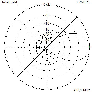
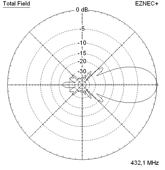
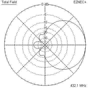
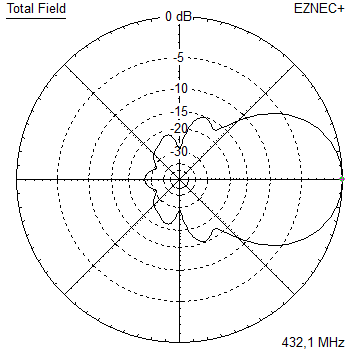
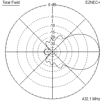
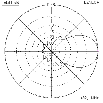
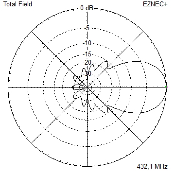
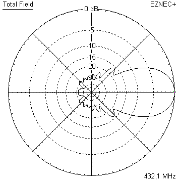
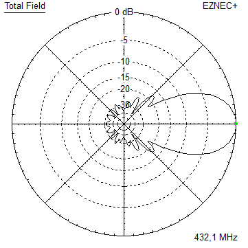
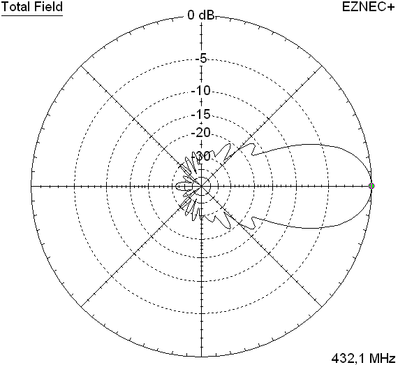
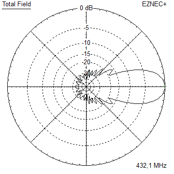
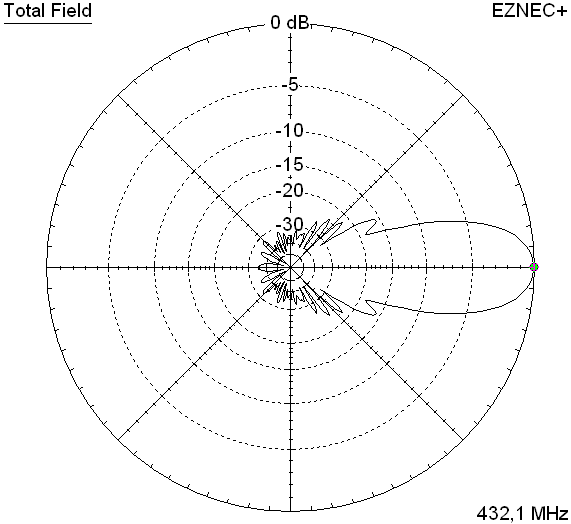
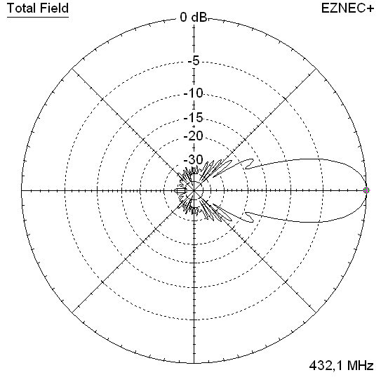
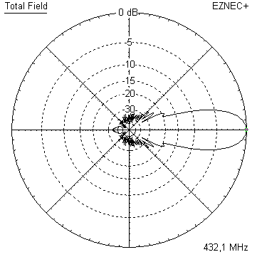
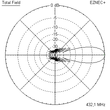
Radiation Pattern Plots
DL6WU Elevation Plot
DL6WU 13 el. specs: with 4.00 mm elements @ 432.1 MHz


13 el. = Gain vs. isotr. Rad.  15.25 dBi
Impedance                      50 ohms
Mechan. Length               2317 mm incl. 2 x 40 mm offset to end of boom
DL6WU 14 el. specs: with 4.00 mm elements @ 432.1 MHz


14 el. = Gain vs. isotr. Rad.  15.64 dBi
Impedance                      50 ohms
Mechan. Length               2588 mm incl. 2 x 40 mm offset to end of boom
DL6WU 15 el. specs: with 4.00 mm elements @ 432.1 MHz


15 el. = Gain vs. isotr. Rad.  15.93 dBi
Impedance                      50 ohms
Mechan. Length               2865 mm incl. 2 x 40 mm offset to end of boom
DL6WU 18 el. specs: with 4.00 mm elements @ 432.1 MHz


18 el. = Gain vs. isotr. Rad.  16.87 dBi
Impedance                      50 ohms
Mechan. Length               3698 mm incl. 2 x 40 mm offset to end of boom
DL6WU 20 el. specs: with 4.00 mm elements @ 432.1 MHz


20 el. = Gain vs. isotr. Rad.  17.35 dBi
Impedance                      50 ohms
Mechan. Length               4253 mm incl. 2 x 40 mm offset to end of boom
DL6WU 24 el. specs: with 4.00 mm elements @ 432.1 MHz


24 el. = Gain vs. isotr. Rad.  18.19 dBi
Impedance                      50 ohms
Mechan. Length               5363 mm incl. 2 x 40 mm offset to end of boom
DL6WU 28 el. specs: with 4.00 mm elements @ 432.1 MHz


13 el. = Gain vs. isotr. Rad.  18.83 dBi
Impedance                      50 ohms
Mechan. Length               6433 mm incl. 2 x 40 mm offset to end of boom
DL6WU 32 el. specs: with 4.00 mm elements @ 432.1 MHz


32 el. = Gain vs. isotr. Rad.  19.36 dBi
Impedance                      50 ohms
Mechan. Length               7583 mm incl. 2 x 40 mm offset to end of boom
How many OMs have been looking up this design?
Geometry

"Ready to saw and drill" data for mounting elements through boom with BC according SM5BSZ's BC.exe:
|
This table is only valid for: Boom shape: square Boom dim: 20 x 20 mm Wall thickn.: 2.0 mm Holes in boom: 6.0 mm Offset rear: 40 mm Offset front: 40 mm |
|
Note: This does include an SBC of 0.0 mm plus a correction for the insulators (v-factor!) of 0.7 mm = 0.7 mm
Note: with through Boom BC it is important to stick to the boom end offsets given below!
Table 1.1 = 13 el. Yagi: 4.0 mm elements through a 20 x 20 x 2 mm boom

Table 1.2 = 14 el. Yagi: 4.0 mm elements through a 20 x 20 x 2 mm boom

Table 1.3 = 15 el. Yagi: 4.0 mm elements through a 20 x 20 x 2 mm boom

Table 1.4 = 18 el. Yagi: 4.0 mm elements through a 20 x 20 x 2 mm boom

Table 1.5 = 20 el. Yagi: 4.0 mm elements through a 20 x 20 x 2 mm boom

Table 1.6 = 24 el. Yagi: 4.0 mm elements through a 20 x 20 x 2 mm boom

Table 1.7 = 28 el. Yagi: 4.0 mm elements through a 20 x 20 x 2 mm boom

Table 1.8 = 32 el. Yagi: 4.0 mm elements through a 20 x 20 x 2 mm boom

Table 1.9 = 4x-Reflector: 4.0 mm elements through a 20 x 20 x 2 mm boom
• Mind to place the reflector wall -41 mm backwards from the single reflectors position!

"Ready to saw and drill" data for mounting elements through boom with BC according SM5BSZ's BC.exe:
|
This table is only valid for: Boom shape: square Boom dim: 25 x 25 mm Wall thickn.: 2.0 mm Holes in boom: 6.0 mm Offset rear: 40 mm Offset front: 40 mm |
|
Note: This does include an SBC of 0.0 mm plus a correction for the insulators (v-factor!) of 0.7 mm = 0.7 mm
Note: with through Boom BC it is important to stick to the boom end offsets given below!
Table 2.1 = 13 el. Yagi: 4.0 mm elements through a 25 x 25 x 2 mm boom

Table 2.2 = 14 el. Yagi: 4.0 mm elements through a 25 x 25 x 2 mm boom

Table 2.3 = 15 el. Yagi: 4.0 mm elements through a 25 x 25 x 2 mm boom

Table 2.4 = 18 el. Yagi: 4.0 mm elements through a 25 x 25 x 2 mm boom

Table 2.5 = 20 el. Yagi: 4.0 mm elements through a 25 x 25 x 2 mm boom

Table 2.6 = 24 el. Yagi: 4.0 mm elements through a 25 x 25 x 2 mm boom

Table 2.7 = 28 el. Yagi: 4.0 mm elements through a 25 x 25 x 2 mm boom

Table 2.8 = 32 el. Yagi: 4.0 mm elements through a 25 x 25 x 2 mm boom

Table 2.9 = 4x-Reflector: 4.0 mm elements through a 25 x 25 x 2 mm boom
• Mind to place the reflector wall -41 mm backwards from the single reflectors position!

Geometry for Imperial Boom Measures
Table 3: 4.0 mm elements through a 3/4 x 3/4 x 1/16 inch boom
"Ready to saw and drill" data for mounting elements through boom with BC according SM5BSZ's BC.exe:
|
This table is only valid for: Boom shape: square Boom dim: 3/4 x 3/4 inch Wall thickn.: 1/16 inch Holes in boom: 6.0 mm Offset rear: 40 mm Offset front: 40 mm |
|
Note: This does include an SBC of 0.0 mm plus a correction for the insulators (v-factor!) of 0.7 mm = 0.7 mm
Note: with through Boom BC it is important to stick to the boom end offsets given below!

Table 4: 4.0 mm elements through a 7/8 x 7/8 x 1/16 inch boom
"Ready to saw and drill" data for mounting elements through boom with BC according SM5BSZ's BC.exe:
|
This table is only valid for: Boom shape: square Boom dim: 7/8 x 7/8 inch Wall thickn.: 1/16 inch Holes in boom: 6.0 mm Offset rear: 40 mm Offset front: 40 mm |
|
Note: This does include an SBC of 0.0 mm plus a correction for the insulators (v-factor!) of 0.7 mm = 0.7 mm
Note: with through Boom BC it is important to stick to the boom end offsets given below!

"Ready to saw and drill" data for mounting elements through boom with BC according SM5BSZ's BC.exe:
|
This table is only valid for: Boom shape: square Boom dim: 1 x 1 inch Wall thickn.: 1/16 inch Holes in boom: 6.0 mm Offset rear: 40 mm Offset front: 40 mm |
|
Note: This does include an SBC of 0.0 mm plus a correction for the insulators (v-factor!) of 0.7 mm = 0.7 mm
Note: with through Boom BC it is important to stick to the boom end offsets given below!
Table 5.1 = 13 el. Yagi: 4.0 mm elements through a 1 x 1 x 1/16 inch boom

Table 5.2 = 14 el. Yagi: 4.0 mm elements through a 1 x 1 x 1/16 inch boom

Table 5.3 = 15 el. Yagi: 4.0 mm elements through a 1 x 1 x 1/16 inch boom

Table 5.4 = 18 el. Yagi: 4.0 mm elements through a 1 x 1 x 1/16 inch boom

Table 5.5 = 20 el. Yagi: 4.0 mm elements through a 1 x 1 x 1/16 inch boom

Table 5.6 = 24 el. Yagi: 4.0 mm elements through a 1 x 1 x 1/16 inch boom

Table 5.7 = 28 el. Yagi: 4.0 mm elements through a 1 x 1 x 1/16 inch boom

Table 5.8 = 32 el. Yagi: 4.0 mm elements through a 1 x 1 x 1/16 inch boom

Table 5.9 = 4x-Reflector: 4.0 mm elements through a 1 x 1 x 1/16 inch boom
• Mind to place the reflector wall -41 mm backwards from the single reflectors position!

DL6WU 16 el. plus 4 Reflectors (like Konni F20)
Current Distribution

Elev. and Az. Plot @ 432.1 MHz


VSWR and Return Loss (S11) dB

Geometry

Table 1: DL6WU 16 el. plus 4 Reflectors, 10 mm elements on a 20 x 20 mm boom:
"Ready to saw and drill" data for mounting elements on boom with standard insulators. BC according DG7YBN:
|
Boom shape: square Boom dim: 20 x 20 mm |
|
Note: This includes a "Segmentation Density Correction" (SBC) of 0.15 mm


Downloads
EZNEC file of this Yagi as 32 el. with 4 mm elements
Element lengths and positions for the NEC model:
Duffy, Owen, VK1OK: DL6WU Long boom Yagi design tools - DL6WU-OD.xls, http://owenduffy.net/antenna/dl6wu/index.htm
EZNEC file of the 16 plus 4 Yagi with 10 mm elements

