-
• Main Page
- • Home
• Antennas - • 432 MHz
- YBN 70-5mA 0.5 m 432 MHz blue print of the YBN 2-5m 50 ohms high F/B direct feed 144 MHz Low Noise Yagi
3D Plot

- YBN 70-8zA 1.5 m high gain 28 ohms Yagi.
A design partly based on the hardware of the WY-7010, turning it into a 8 ele. 28 ohms Yagi with cleaner pattern, +1.8 dB gain and better VSWR.
Azimuth Plot
- YBN 70-14wzTune up your 19 ele. Tonna!
A design based on the hardware of the F9FT, turning it into a 14 ele. OWL with cleaner pattern, +0.3 dB gain and SWR less than 1.2 from 430 to 440 MHz
Azimuth Plot
- YBN 70-14+4wA 3.2 m very wideband 50 ohms Yagi with reflector wall that covers the whole 70 cm band with ease
Elevation Plot

- GTV 70-2wA 0.14 m GTV useful for portable operation and up to the satellit band and handheld activities of any kind
Elevation Plot

- GTV 70-3wA 0.21 m GTV useful for portable operation and up to the satellit band and lower noise stacks of any kind
Elevation Plot

- GTV 70-4mA 0.34 m GTV useful for portable operation up to the satellit band and lower noise stacks of any kind
Elevation Plot
- GTV 70-7wA 0.96 m GTV useful for portable operation up to the satellit band and lower noise stacks of any kind
Elevation Plot
- GTV 70-7nA 1.1 m 432 MHz blue print of the low impedance, yet 50 ohms direct feed 144 MHz Low Noise Yagi introduced in Dubus 1/2013
Elevation Plot
- GTV 70-8nA 1.3 m 432 MHz GTV with high gain but low backlobe volume. Makes a very compact 4 Yagi bay for QRP EME or contesting.
Elevation Plot
- GTV 70-9wA 1.44 m GTV ment to be useful as a vertical stack for contesting or be an ideal small size portable Yagi
Elevation Plot

- GTV 70-10wA 1.63 m GTV useful for portable operation up to the satellit band and lower noise stacks of any kind
Elevation Plot
- GTV 70-11wA 2.01 m GTV ment to be useful as a vertical stack for contesting or be an ideal small size portable Yagi or minimum size EME 4 bay
Elevation Plot
- GTV 70-13mA 2.5 m GTV ment to be useful as a vertical stack for contesting or be an ideal small size portable Yagi or minimum size EME 4 bay
Elevation Plot
- GTV 70-14m2.9 m version of the low impedance, yet 50 ohms direct feed Low Noise Yagi with bent DE introduced in Dubus 1/2013
Elevation Plot
- GTV 70-17m3.7 m version of the low impedance, yet 50 ohms direct feed Low Noise Yagi with bent DE introduced in Dubus 1/2013
Elevation Plot

- GTV 70-18w4.0 m version of the low impedance, yet 50 ohms direct feed Low Noise Yagi with bent DE introduced in Dubus 1/2013
Elevation Plot
- GTV 70-19m4.2 m version of the low impedance, yet 50 ohms direct feed Low Noise Yagi with bent DE introduced in Dubus 1/2013
Elevation Plot

- GTV 70-21n4.7 m version of the low impedance, yet 50 ohms direct feed Low Noise Yagi with bent DE introduced in Dubus 1/2013
Elevation Plot

- GTV 70-23m5.3 m version of the low impedance, yet 50 ohms direct feed Low Noise Yagi with bent DE introduced in Dubus 1/2013
Elevation Plot
- GTV 70-25m5.9 m version of the low impedance, yet 50 ohms direct feed Low Noise Yagi with bent DE introduced in Dubus 1/2013
Elevation Plot
- GTV 70-30m7.3 m version of the low impedance, yet 50 ohms direct feed Low Noise Yagi with bent DE introduced in Dubus 1/2013
Elevation Plot
- GTV 70-34w8.5 m version of the low impedance, yet 50 ohms direct feed Low Noise Yagi with bent DE introduced in Dubus 1/2013
Elevation Plot
- GTV 70-46w12.0 m version of the low impedance, yet 50 ohms direct feed Low Noise Yagi with bent DE introduced in Dubus 1/2013
Elevation Plot

- DL6WU YagisThe DL6WU Longyagi Series
Sample plot: 32 el. plus 4 x reflector
Elevation Plot

- YBN 70-5m
GTV 70-13m Yagi 'Aquarius'
with bent Driven ElementEME and weak signal operation trimmed but OWA character Yagi ... strictly G/T breeding
This Yagi has very low back lobes for its length. It comes with lower Antenna Temperature then most at given
length but provides full gain. Hence it delivers a respectable G/Ta. It may serve as single antenna for portable
use and certainly make a useful 4 x vertical stack. It makes a quiet contest antenna due to its
high F/B. The bent DE (K6STI style) transforms from approx. 17 ohms to 50 ohms at feed point.
Date of issuing this design : 13th of March 2020
A crop of the 09/2024 EME newsletter shows its potential and DL1VPZ's skills as the operator:

3D Pattern

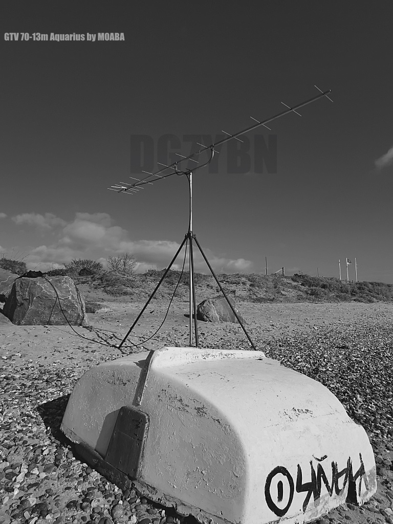
GTV 70-13m Aquarius built by Thomas, M0ABA

And an easy EME QSO in WSJT JT65 with antenna not even positioned to moon carefully.

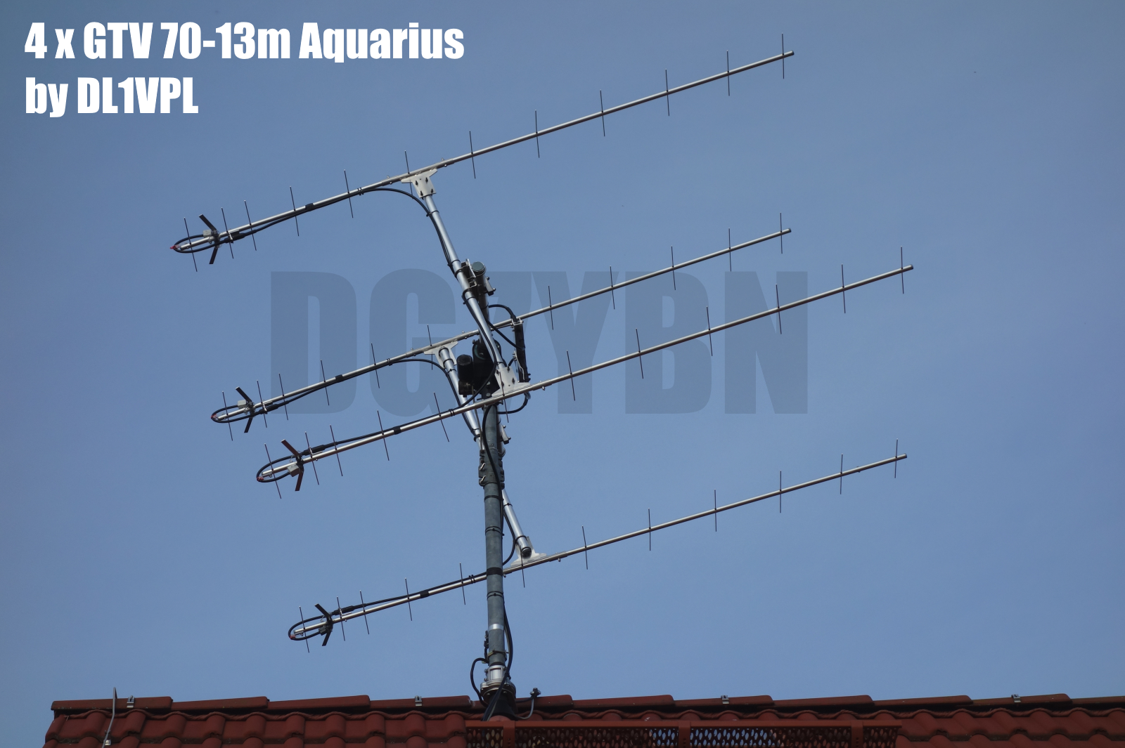
4 x GTV 70-13m Aquarius built by Darek, SQ3GLS

4 x GTV 70-13m Aquarius built by Thomas, DL1VPL

For larger view click here
His blade dipole measures a little different geometry than posted below:
Bending angle: 18 deg., length of bent part (forward side): 118 mm (comp. drawing 129 mm),
check measure (width 90 deg. to boom per arm): approx. 142 mm (comp. drawing 156 mm).

sheet is placed straight underneath the boom and long enough to put some distance in
before end of pole tube.
Photo Credit: Thomas, DL1VPL. Tnx Thomas!
Name giving and occasion
Apollo 13 was a 1970 manned spaceflight with the objective to land on the moon:
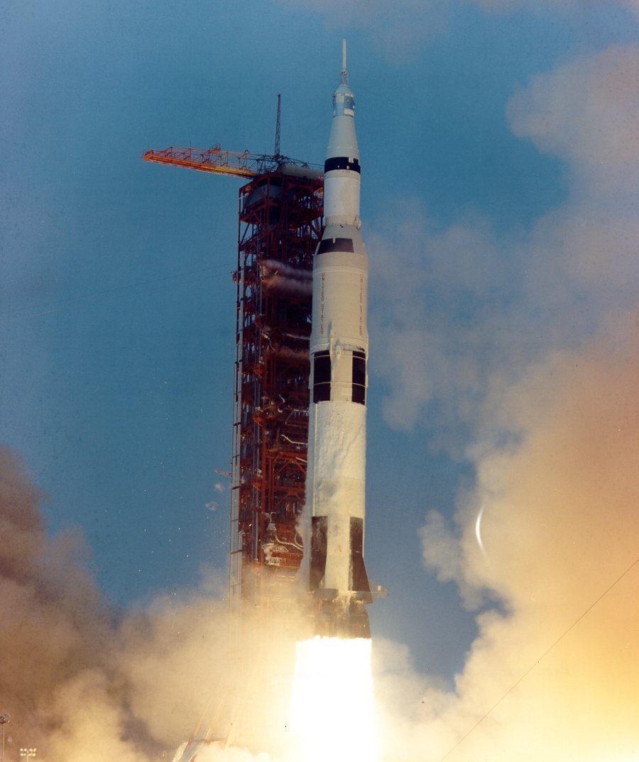
Saturn V rocket SA-508 carried Service Module with Command Modue Odyssee, Lunar Module Aquarius.
Launch was on schedule on April 11, 1970 at 19:13:00 UTC. At flight time 55:54:53 in a distance of 330,000 km
from Earth the exident occured.
The systems of the CM had to be shut down to spare any remaining air and power for reentry.
So the crew had to transfer to the lunar module Aquarius as their life boat.
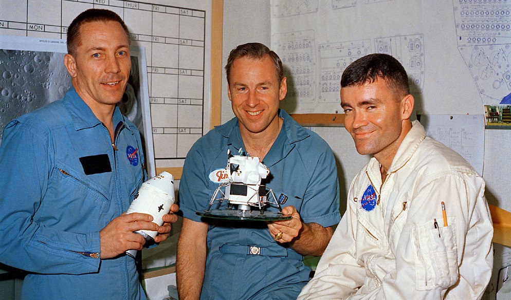
Left: Jack Swigert, Jim Lovell, and Fred Haise one day before launch, 10 April 1970. Research by Ed Hengeveld.
Source: crop of www.hq.nasa.gov/alsj/a13/ap13-S70-34767.jpg
Right: Saturn V Apollo 13 launch, Scan by Kipp Teague, Nasa
Source: www.hq.nasa.gov/alsj/a13/ap13-S70-34853.jpg
|
|
Audio on www.DG7YBN.de |
Listen to the audio of the radio contact between Apollo 13 and Houston Nasa Ground Control at the
moment the probleme was discovered at 55 h 54 min of flight time in a distance of 330,000 k from earth.
This is an original sound file from the Nasa Project Apollo Archive ( = source):
"... we had a pretty large bang associated with the CAUTION AND WARNING there...."

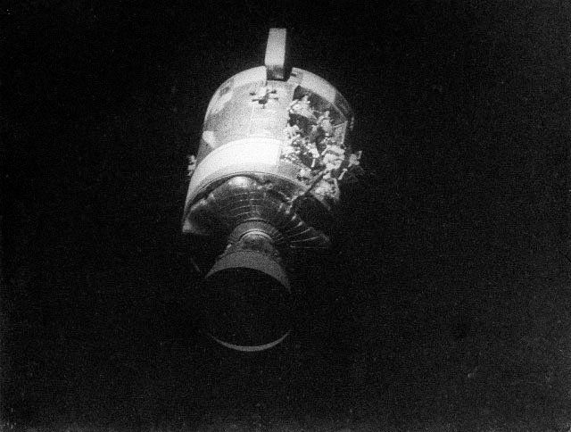
Left: Aquarius, Source: Project_Apollo_Archive AS13-59-8566
Right: AS13-59-8500A (17 April 1970) view of the severely damaged Apollo 13 Service Module (SM)
photographed from the Lunar Module/Command Module
Source: https://spaceflight.nasa.gov/gallery/images/apollo/apollo13/html/as13-59-8500a.html
Joe Kerwin, Capsule Communicator (CAPCOM): "Farewell, Aquarius, and we thank you."
as she was set adrift after keeping the astronauts safe.
Current distribution

Performance Data
Specs: with 4 mm elements @ 432.1 MHz
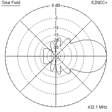
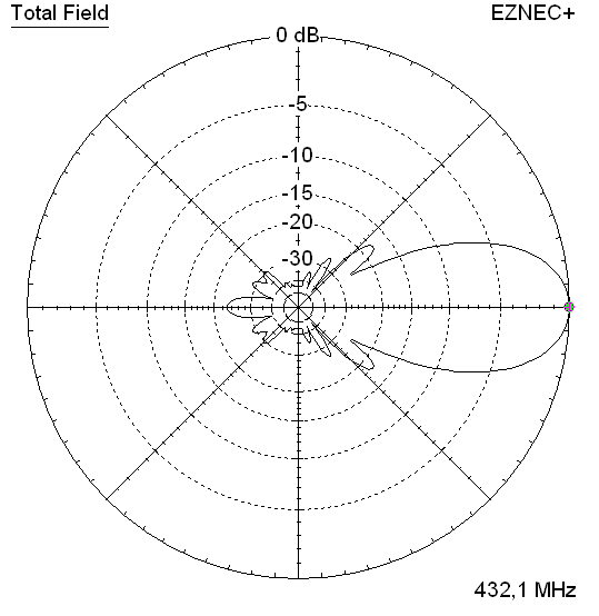
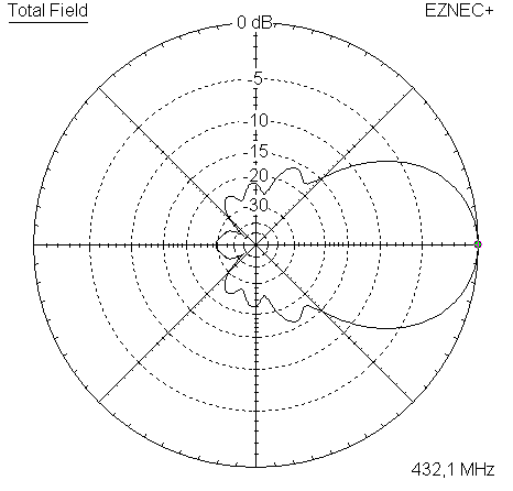
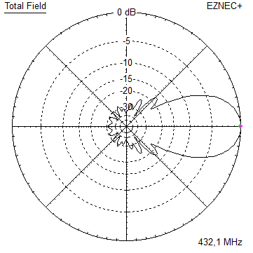
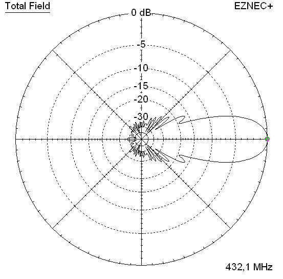
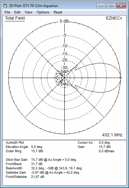
Gain vs. isotr. Rad.  15.7 dBi
Gain vs. Dipole       13.6 dBD
-3 dB E-plane         31.7 deg.
-3 dB H-plane         34.6 deg.
F/B                  -31.7 dB
F/R                  -28.8 dB
Impedance               50 ohms
Mechan. Length        2568 mm incl. 2 x 40 mm stand off
Electr. Length        3.59 λ

VSWR Bandwidth        1:1.5 (at 435.0 MHz as in VE7BQH Antenna Table)

Stacking dist. h-pol.
top-to-bottom         1.21 m or 3,97 ft
side-by-side          1.07 m or 3.51 ft
How many OMs have been looking up this design?
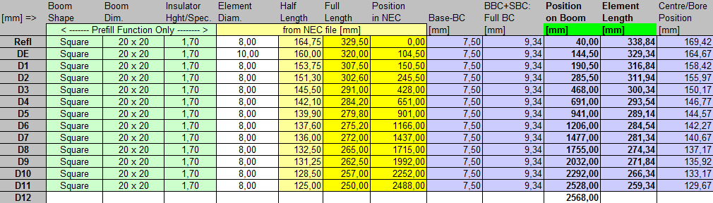
Geometry

GTV 70-13m, 4 mm elements through square boom:
"Ready to saw and drill" data for mounting elements through boom with BC according SM5BSZ's BC.exe:
Note: with through Boom BC it is important to stick to the boom end offsets given below!
Metric Boom 20 x 20 x 2 mm
|
This table is only valid for: Boom shape: square Boom dim: 20 x 20 mm Wall thickn.: 2.0 mm Holes in boom: 6.0 mm Offset rear: 40 mm Offset front: 40 mm |
|

Note: with through Boom BC it is important to stick to the boom end offsets given below!

Metric Boom 25 x 25 x 2 mm
|
This table is only valid for: Boom shape: square Boom dim: 25 x 25 mm Wall thickn.: 2.0 mm Holes in boom: 6.0 mm Offset rear: 40 mm Offset front: 40 mm |
|
Note: with through Boom BC it is important to stick to the boom end offsets given below!

Imperial Boom 1"
|
This table is only valid for: Boom shape: square Boom dim: 1 x 1 inch Wall thickn.: 1.6 mm Holes in boom: 6.0 mm Offset rear: 40 mm Offset front: 40 mm |
|
Note: All the above include a "Segmentation Density Correction" (SBC) of 1.14 mm plus an offset of 0.70 mm per element = 1.84 mm
for compensation of the insulators (7arrays.com
Note: with through Boom BC it is important to stick to the boom end offsets given below!
Read abt. the SBC here


GTV 70-13m, 4 mm elements through round boom:
"Ready to saw and drill" data for mounting elements through boom with BC according SM5BSZ's BC.exe:
Note: with through Boom BC it is important to stick to the boom end offsets given below!
Metric Boom 20 x 1.5 mm
|
This table is only valid for: Boom shape: rounde Boom dim: 20 mm Wall thickn.: 1.5 mm Holes in boom: 6.0 mm Offset rear: 40 mm Offset front: 40 mm |
|
Note: with through Boom BC it is important to stick to the boom end offsets given below!


Ø8 mm Elements - On Boom - Dimensions (BC acc. DG7YBN)

|
Ele. 8.0 mm DE 10 mm Boom 20 x 20 mm |
"Ready to saw and drill" data for mounting elements on boom with BC according DG7YBN for standard insulators as sold by WiMo, Tino's Funkshop, HF Kits.nl, 7arrays:
Includes an SBC of 1.84 mm
Ø8 mm Elements - On Boom - Dimensions (BC acc. DG7YBN)

|
Ele. 8.0 mm DE 10 mm Boom 25 x 25 mm |
"Ready to saw and drill" data for mounting elements on boom with BC according DG7YBN for standard insulators as sold by WiMo, Tino's Funkshop, 7arrays:
Includes an SBC of 1.84 mm

For making of a 'Blade Dipole'
Sketch of Bent Dipole

The real blade dipole. The bending angle is much less then for the GTV 70-14 ... 19 models.

| • Drawing of the blade dipole as PDF (tnx Thomas, M0ABA for measuring this!) |
|

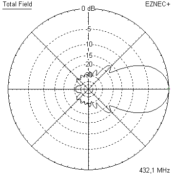
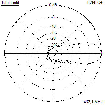
Radiation Pattern and VSWR Plots
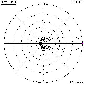
Elevation and Azimuth plot at 432.1 MHz (4 mm ele.)

SWR and Return Loss plots - simulated with 4nec2
(I have settled the best Return Loss a bit higher for giving headroom in wet weather)
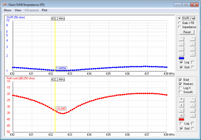
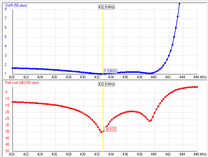
Return Loss and VSWR plots by M0ABA: -33 dB at 432.2 MHz and a fine coincidence simulation to real Yagi


GTV70-13m prototype built by Thomas, DL1VPL

GTV 70-13m Aquarius with Folded Dipole

The straight split bent dipole can be replaced with a bent folded dipole like in any non-bent Yagi design.
In doing so the transformation ratio of 1:4 remains. The bent folded dipole versions impedance is 200 ohms.
The folded dipole itself is of Ø 6 mm; I recommend an 'elements through boom' built.
So that the folded dipole is centered in the element plane for best symmetry in the elevation pattern.
Geometry of the Folded Dipole
In the model we use the center of the tube, regardless of its actual diameter.
With this height is 44 mm, span width is 314 mm. Adding the real diameter of 6 mm we end up with
inner height = 38 mm, outer span width = 320 mm, see sketch


Note Folded Dipole mounting in plastic brackets compensation
Whatever plastic block is used to suspend or mount the dipoles wires will need to be compensated
by adding ~ 0.1 mm per millimeter of wire running in plastic. If you attach a 20 mm plastic block on top
of the boom to lead the dipoles upper wire a length of 2.0 mm / 2 = 1.0 mm needs to be added to the dipoles
span width. Assumed it runs free of contact to plastic on the down side.
We use factor 1/2 in a folded dipole then since it is a full wave loop.
Same applies to any BC if the wires run very close (~ < 3 mm) to the boom.
Folded dipoles for the GTV70-11w built by Rob, PD7RKZ
Dipoles bent to above dimensions, using a plastic dipole boxes sold by www.nuxcom.de
and 'smeared (all) well with Plast2000 in the boxes'.


Photo: with kind permission of Rob, PD7RKZ
Stacking
As on 432 MHz the Y-factor = T_earth / T_sky is so high, I see little chances to
improve an array's RX performance by using "Over Stacking" distances. However, depending on
the level of local QRM it might be worthwhile to try a decreased distance, especially in the H-plane.
Stacking Dist.    DL6WU Formula
H-plane               1.251 m
E-plane               1.167 m
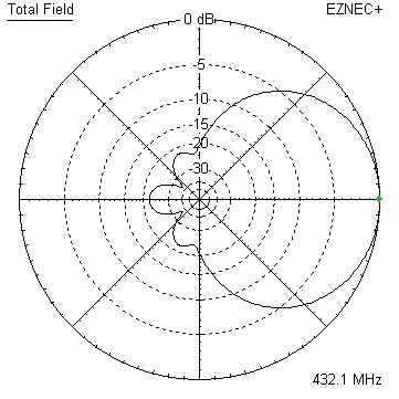
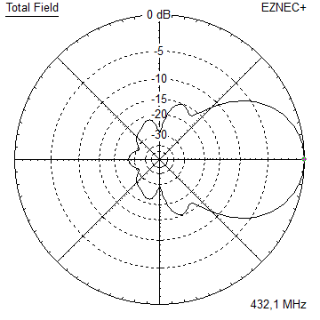
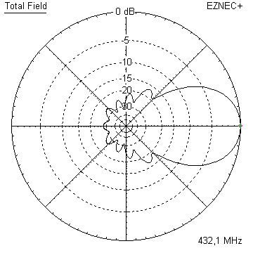
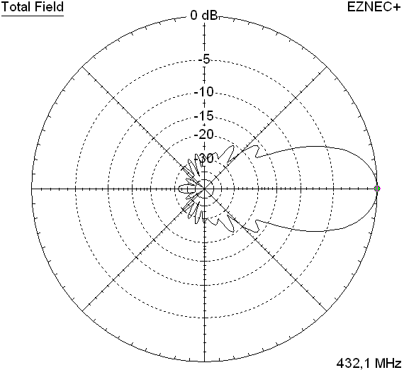
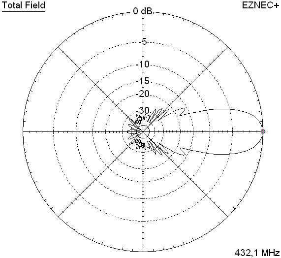
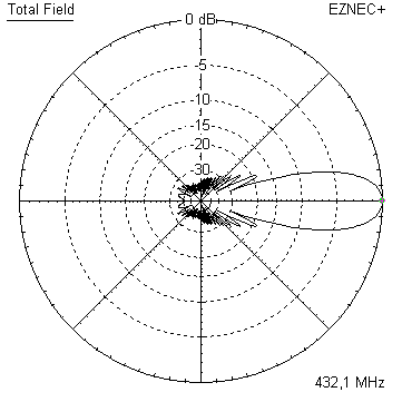
A 4 Yagi bay
Antenna View, EZNEC+ v5

Elev. Plot
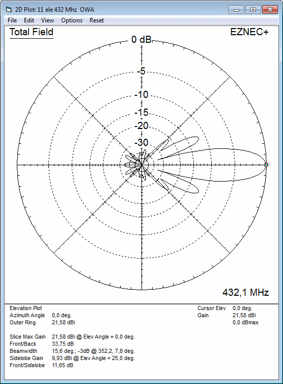
Azim. Plot

Gain vs. isotr. Rad.  21.6 dBi
Gain vs. Dipole       19.4 dBD
-3 dB H-plane, appr.  15.6 deg.
-3 dB E-plane, appr.  14.6 deg.
F/B                  -33.7 dB
F/R                  -32.6 dB
T_ant                 59.1 K*
G/T                   3.83 dB*

at Tsky = 27 K, Tearth = 1800 K as in newer VE7BQH Antenna Table
3D pattern plot with 4nec2's 3D viewer

Antenna G/T with AGTC lite:

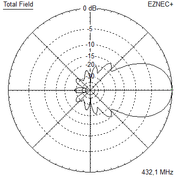
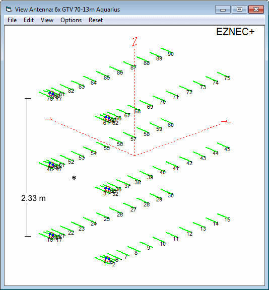
A 6 Yagi bay
Antenna View, EZNEC+ v5
Pattern Plot (4nec2) : 23.3 dBi
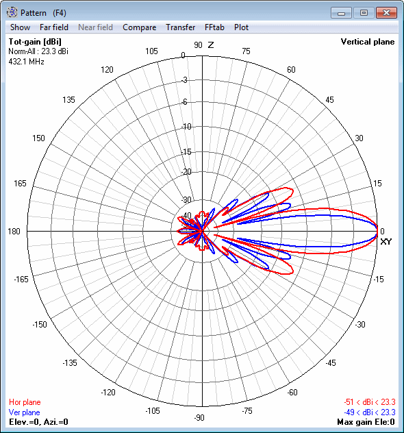
3D pattern plot with 4nec2

Symmetrising 50 to 50 ohms feedline to 432 MHz Bent DE
The principle is similar to the 1/4 Lambda coax. Adding 2 x 1/4 Lambda or a half wave line does not change anything but allows
to form a gentle bow below the boom or until behind the Reflector. Follow practical construction hints on "Building a Yagi" page.


 Attenzione!
Take care when lengthening the coax, measure the actual electrical length instead of considering v-factors specified in a catalogue only.
Attenzione!
Take care when lengthening the coax, measure the actual electrical length instead of considering v-factors specified in a catalogue only.A good choice may be the diam. 5 mm PTFE coax RG-142 B/U: real resonate length (432.2 MHz as 3/4 Lambda) shield-shield is around 348 mm
 Find more information on Phasing & Matching Lines page
 73, Hartmut, DG7YBN