-
• Main Page
- • Home
• Antennas - • 432 MHz
- YBN 70-5mA 0.5 m 432 MHz blue print of the YBN 2-5m 50 ohms high F/B direct feed 144 MHz Low Noise Yagi
3D Plot

- YBN 70-8zA 1.5 m high gain 28 ohms Yagi.
A design partly based on the hardware of the WY-7010, turning it into a 8 ele. 28 ohms Yagi with cleaner pattern, +1.8 dB gain and better VSWR.
Azimuth Plot
- YBN 70-14wzTune up your 19 ele. Tonna!
A design based on the hardware of the F9FT, turning it into a 14 ele. OWL with cleaner pattern, +0.3 dB gain and SWR less than 1.2 from 430 to 440 MHz
Azimuth Plot
- YBN 70-14+4wA 3.2 m very wideband 50 ohms Yagi with reflector wall that covers the whole 70 cm band with ease
Elevation Plot

- GTV 70-2wA 0.14 m GTV useful for portable operation and up to the satellit band and handheld activities of any kind
Elevation Plot

- GTV 70-3wA 0.21 m GTV useful for portable operation and up to the satellit band and lower noise stacks of any kind
Elevation Plot

- GTV 70-4wA 0.33 m wideband GTV useful for portable operation up to the satellit band and lower noise stacks of any kind
Elevation Plot
- GTV 70-4mA 0.34 m GTV useful for portable operation up to the satellit band and lower noise stacks of any kind
Elevation Plot
- GTV 70-7wA 0.96 m GTV useful for portable operation up to the satellit band and lower noise stacks of any kind
Elevation Plot
- GTV 70-7nA 1.1 m 432 MHz blue print of the low impedance, yet 50 ohms direct feed 144 MHz Low Noise Yagi introduced in Dubus 1/2013
Elevation Plot
- GTV 70-8nA 1.3 m 432 MHz GTV with high gain but low backlobe volume. Makes a very compact 4 Yagi bay for QRP EME or contesting.
Elevation Plot
- GTV 70-9wA 1.44 m GTV ment to be useful as a vertical stack for contesting or be an ideal small size portable Yagi
Elevation Plot

- GTV 70-10wA 1.63 m GTV useful for portable operation up to the satellit band and lower noise stacks of any kind
Elevation Plot
- GTV 70-11wA 2.01 m GTV ment to be useful as a vertical stack for contesting or be an ideal small size portable Yagi or minimum size EME 4 bay
Elevation Plot
- GTV 70-13mA 2.5 m GTV ment to be useful as a vertical stack for contesting or be an ideal small size portable Yagi or minimum size EME 4 bay
Elevation Plot
- GTV 70-14m2.9 m version of the low impedance, yet 50 ohms direct feed Low Noise Yagi with bent DE introduced in Dubus 1/2013
Elevation Plot
- GTV 70-17m3.7 m version of the low impedance, yet 50 ohms direct feed Low Noise Yagi with bent DE introduced in Dubus 1/2013
Elevation Plot

- GTV 70-18w4.0 m version of the low impedance, yet 50 ohms direct feed Low Noise Yagi with bent DE introduced in Dubus 1/2013
Elevation Plot
- GTV 70-19m4.2 m version of the low impedance, yet 50 ohms direct feed Low Noise Yagi with bent DE introduced in Dubus 1/2013
Elevation Plot

- GTV 70-21n4.7 m version of the low impedance, yet 50 ohms direct feed Low Noise Yagi with bent DE introduced in Dubus 1/2013
Elevation Plot

- GTV 70-23m5.3 m version of the low impedance, yet 50 ohms direct feed Low Noise Yagi with bent DE introduced in Dubus 1/2013
Elevation Plot
- GTV 70-25m5.9 m version of the low impedance, yet 50 ohms direct feed Low Noise Yagi with bent DE introduced in Dubus 1/2013
Elevation Plot
- GTV 70-30m7.3 m version of the low impedance, yet 50 ohms direct feed Low Noise Yagi with bent DE introduced in Dubus 1/2013
Elevation Plot
- GTV 70-34w8.5 m version of the low impedance, yet 50 ohms direct feed Low Noise Yagi with bent DE introduced in Dubus 1/2013
Elevation Plot
- GTV 70-46w12.0 m version of the low impedance, yet 50 ohms direct feed Low Noise Yagi with bent DE introduced in Dubus 1/2013
Elevation Plot

- DL6WU YagisThe DL6WU Longyagi Series
Sample plot: 32 el. plus 4 x reflector
Elevation Plot

- YBN 70-5m
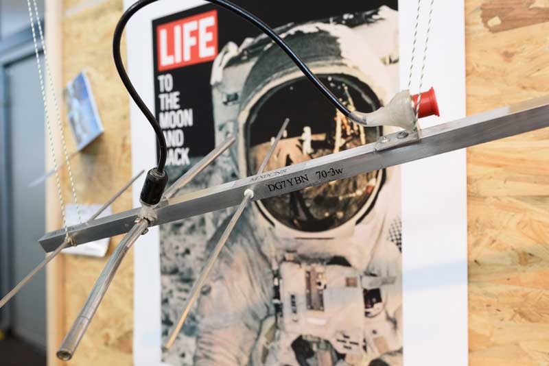
GTV 70-3w Yagi with bent Driven Element
(EME) - SSB band, but fully usable up to 440 MHz ( < VSWR 1.2)
This little Yagi has a high F/B, which makes it quite useful as a contest stack, for SOTA use or whatever.
The bent DE (K6STI style) transforms from approx. 17 ohms to 50 ohms at feed point. Note: for this design
I had no interest in competing in yielding highest gain or so but made a feasible design that delivers in all
conditions. So if you compare gain and features please take into account the boom length and VSWR bandwidth.
 The GTV 70-3 was the worlds tiniest EME Yagi until it was matched by the GTV 70-2m
Download the Ham Radio 2016 Flyer "Challenge 70 cm QRP EME - You can do it!"

The M0ABA/MX0CNS built GTV70-3w on the Ham Radio 2016, photo: YO3ITI, tnx Miron
3D Radation Pattern ... and built by Thomas, M0ABA


After success with the GTV70-4m Thomas, M0ABA @ MX0CNS runs 'Operation Wavelet' to find the bottom line:
2016-04-11: 20-08 UTC - Mission accomplished : MX0CNS and OK1DFC did a QSO.
Zdenek, OK1DFC asked for a sked and would you believe it, I was just 8 minutes late on the HB9Q logger and the QSO wasalready done and dusted by then. Zdenek, OK1DFC: 'Hi Hartmut, here is print screen of QSO, it was very easy, for first
shot and done.' OK1DFC operates a 10 m dish, 1,5 kW out, 0.2 dB NF LNA, link to Zdenek's 432 MHz EME web
See how MX0CNS was copied at OK1DFC


2016-04-10: 08-43 UTC - Mission accomplished : MX0CNS and DL7APV did a QSO.
So now even the all amateur antennas EME QSO is done.
Bernd, DL7APV used 2 receiver lines for this: Upper shot: TR7 and computer 1, lower shot: FT897 and computer 2Signal levels peaking -27 dB. Not to bad, hi, given the EIRP < 340 W at MX0CNS.
See how MX0CNS was copied at DL7APV


2016-04-09: 15-46 UTC - Mission accomplished : MX0CNS and PI9CAM did a random QSO.
The 25 m dish at Dwingeloo helped to make this real. Big Tnx to the crew at PI9CAM!!
According Dick, PA2DW @ PI9CAM this is the smallest station they ever worked via EME.Dwingeloo-Radioteleskop: image 'DRT_2006_06.jpg' by Harm_Munk, https://de.wikipedia.org/wiki/Dwingeloo-Radioteleskop
place mouse over thumbmail to enlarge
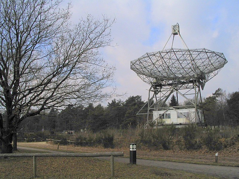
Dwingeloo-Radioteleskop, Source wikipedia, photographer: Harm Munk

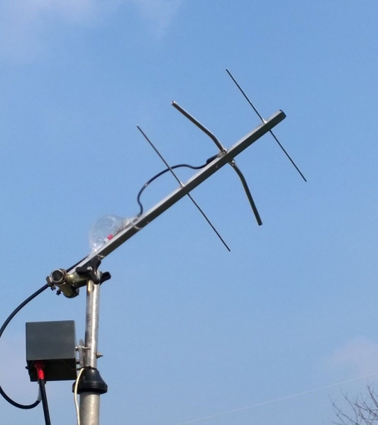
The GTV 70-3w with PreAmp at feed built by Thomas, M0ABA

specJT screenshot: traces of PI9CAM at MX0CNS, by Thomas, M0ABA
link to "C.A. Muller Radio Astronomy Station" = camras.nl, the initiative that restored the telescope
Only 60 W at feed = EIRP at MX0CNS < 340 W (!). A WSJT screenshot at MX0CNS

2016-03-11 : 15:06 UTC - First ever EME signal decode with the GTV70-3w, though much Faraday rotation was present


Look out for us on HB9Q logger and help make this happen please!
see Essex DX group on facebook as wellAnd on 2016-03-12 first fine decodes of DL7APV at -24 ... - 26 dB, not bad at all!

Wires in 4nec2's 3D viewer and elevation pattern

This website has been viewed by how many 70 cm enthusiasts since Febr. 2016?
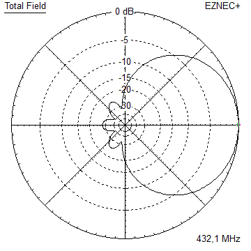
Performance Data
Gain vs. isotr. Rad.   7.5 dBi
Gain vs. Dipole        5.4 dBD
-3 dB E-plane         66.5 deg.
-3 dB H-plane        111.4 deg.
F/B                  -16.7 dB
F/R                  -16.7 dB
Impedance               50 ohms
Mechan. Length         203 mm ex. boom end offsets
Electr. Length        0.29 λ

Stacking Dist. h-pol.
top-to-bottom         appr. 0.5 m see chapter stacking
side-by-side          appr. 0.45 m
Geometry
EZNEC wire table for Ø 4 mm elements
For the SBC the frequency impact is nill here
Using the proposed through boom insulators add a fixed offset on to BC of 0.7 mm so that total SBC = 0.7 mm
• "Ready to saw and drill" data for mounting 4.0 mm elements insulated through boom with SM5BSZ's BC.exe applied
Note that with an elements insulated through boom built for best results boomlength and positions to first /last element must be kept as given.
Because the position of an element relative to its nearer boom end is a serious parameter in the BC.exe.
This table is only valid for:
Boom shape: square
Boom dim: 5/8 in x 5/8 in (15.9 mm)
Wall thickn.: 1.6 mm
Holes in boom: 6.0 mm
Offset rear: 300 mm
Offset front: 40 mm
• Data set for 4 mm elements with rear boom end offset = 300 mm for formast mounting

• Same with a 15 x 15 x 1 mm boom

• Same with a 20 x 20 x 2 mm boom

The Drivers diameter is 10 mm for all examples. Use EZNEC's Auto-Segmentation at 1050 MHz.
A simple symmetrising member may be made from a 3 x 1/4 Lambda line grounded at the far side with
N-flange-bushing and an aluminium plate and ferrite added as close as possible to the DE, see below.
• Take a look at photos explaining how to build this Yagi on the GTV 70-4m website
Sketch of Bent Dipole

Pattern and VSWR Plots
SWR and Return Loss plots - simulated with 4nec2

Downloads
EZNEC file of this Yagi with 4 mm elements
Stacking
• For Yagis of a length less approximately 2 wL the DL6WU formula does not deliver best performance.
Hence the stacking distances for the GTV 70-3w are 'handmade', optimised using NEC.
• For very small Yagis the optimum stacking distances are that low, that mutual coupling between
the individual Yagis becomes a serious effect. Which spoils the VSWR. So that either an adaption of the Yagis
must take place or we just live with less Return Loss if practicable.
Azimuth plot and data of 2 x vertical stack of GTV70-3w Yagis at 480 mm
Yaigs not modified. VSWR < 1.2 for 430 - 435 MHz and < 1.3 at 440 MHz

Stacking Dist.  - NEC optimised small Yagi distance -
H-plane               0.-- m
E-plane               0.480 m
Elevation plot and data of 4 x vertical stack of GTV 70-3w Yagis at 495 mm each

Stacking Dist.  - NEC optimised small Yagi distance -
H-plane               0.-- m
E-plane               0.510 m
Symmetrising 50 to 50 ohms Feedline to 432 MHz Bent DE
The principle is similar to the 1/4 Lambda coax. Adding 2 x 1/4 Lambda or a half wave line does not change anything but allows
to form a gentle bow below the boom or until behind the Reflector. Follow practical construction hints on "Building a Yagi" page.

 Attenzione!
Take care when lengthening the coax, measure the right length instead of refering to given v-factors only.
Attenzione!
Take care when lengthening the coax, measure the right length instead of refering to given v-factors only.A good choice may be the diam. 5 mm PTFE coax RG-142 B/U: real resonate length (432.2 Mhz as 3/4 Lambda) shield-shield is around 348 mm
 Find more information on Phasing & Matching Lines page
 73, Hartmut, DG7YBN