-
• Main Page
- • Home
• Antennas - • 432 MHz
- YBN 70-5mA 0.5 m 432 MHz blue print of the YBN 2-5m 50 ohms high F/B direct feed 144 MHz Low Noise Yagi
3D Plot

- YBN 70-8zA 1.5 m high gain 28 ohms Yagi.
A design partly based on the hardware of the WY-7010, turning it into a 8 ele. 28 ohms Yagi with cleaner pattern, +1.8 dB gain and better VSWR.
Azimuth Plot
- YBN 70-14wzTune up your 19 ele. Tonna!
A design based on the hardware of the F9FT, turning it into a 14 ele. OWL with cleaner pattern, +0.3 dB gain and SWR less than 1.2 from 430 to 440 MHz
Azimuth Plot
- YBN 70-14+4wA 3.2 m very wideband 50 ohms Yagi with reflector wall that covers the whole 70 cm band with ease
Elevation Plot

- GTV 70-2wA 0.14 m GTV useful for portable operation and up to the satellit band and handheld activities of any kind
Elevation Plot

- GTV 70-3wA 0.21 m GTV useful for portable operation and up to the satellit band and lower noise stacks of any kind
Elevation Plot

- GTV 70-4wA 0.33 m wideband GTV useful for portable operation up to the satellit band and lower noise stacks of any kind
Elevation Plot
- GTV 70-4mA 0.34 m GTV useful for portable operation up to the satellit band and lower noise stacks of any kind
Elevation Plot
- GTV 70-7wA 0.96 m GTV useful for portable operation up to the satellit band and lower noise stacks of any kind
Elevation Plot
- GTV 70-7nA 1.1 m 432 MHz blue print of the low impedance, yet 50 ohms direct feed 144 MHz Low Noise Yagi introduced in Dubus 1/2013
Elevation Plot
- GTV 70-8nA 1.3 m 432 MHz GTV with high gain but low backlobe volume. Makes a very compact 4 Yagi bay for QRP EME or contesting.
Elevation Plot
- GTV 70-9wA 1.44 m GTV ment to be useful as a vertical stack for contesting or be an ideal small size portable Yagi
Elevation Plot

- GTV 70-10wA 1.63 m GTV useful for portable operation up to the satellit band and lower noise stacks of any kind
Elevation Plot
- GTV 70-11wA 2.01 m GTV ment to be useful as a vertical stack for contesting or be an ideal small size portable Yagi or minimum size EME 4 bay
Elevation Plot
- GTV 70-13mA 2.5 m GTV ment to be useful as a vertical stack for contesting or be an ideal small size portable Yagi or minimum size EME 4 bay
Elevation Plot
- GTV 70-14m2.9 m version of the low impedance, yet 50 ohms direct feed Low Noise Yagi with bent DE introduced in Dubus 1/2013
Elevation Plot
- GTV 70-17m3.7 m version of the low impedance, yet 50 ohms direct feed Low Noise Yagi with bent DE introduced in Dubus 1/2013
Elevation Plot

- GTV 70-18w4.0 m version of the low impedance, yet 50 ohms direct feed Low Noise Yagi with bent DE introduced in Dubus 1/2013
Elevation Plot
- GTV 70-19m4.2 m version of the low impedance, yet 50 ohms direct feed Low Noise Yagi with bent DE introduced in Dubus 1/2013
Elevation Plot

- GTV 70-21n4.7 m version of the low impedance, yet 50 ohms direct feed Low Noise Yagi with bent DE introduced in Dubus 1/2013
Elevation Plot

- GTV 70-23m5.3 m version of the low impedance, yet 50 ohms direct feed Low Noise Yagi with bent DE introduced in Dubus 1/2013
Elevation Plot
- GTV 70-25m5.9 m version of the low impedance, yet 50 ohms direct feed Low Noise Yagi with bent DE introduced in Dubus 1/2013
Elevation Plot
- GTV 70-30m7.3 m version of the low impedance, yet 50 ohms direct feed Low Noise Yagi with bent DE introduced in Dubus 1/2013
Elevation Plot
- GTV 70-34w8.5 m version of the low impedance, yet 50 ohms direct feed Low Noise Yagi with bent DE introduced in Dubus 1/2013
Elevation Plot
- GTV 70-46w12.0 m version of the low impedance, yet 50 ohms direct feed Low Noise Yagi with bent DE introduced in Dubus 1/2013
Elevation Plot

- DL6WU YagisThe DL6WU Longyagi Series
Sample plot: 32 el. plus 4 x reflector
Elevation Plot

- YBN 70-5m
GTV 70-11w Yagi with bent Driven Element
Wideband OWA style medium size Yagi with focus on EME + SSB band but covering 430-440 MHz
This Yagi has very low back lobes for its length. It may serve as single antenna for portable
use and certainly make a useful 4 x vertical stack. It makes a quiet contest antenna due to its
high F/B. The bent DE (K6STI style) transforms from approx. 17 ohms to 50 ohms at feed point.
Find the GTV 70-11w listed in the VE7BQH G/T tables
8 x GTV 70-11w at JE2UFF Oct. 2020
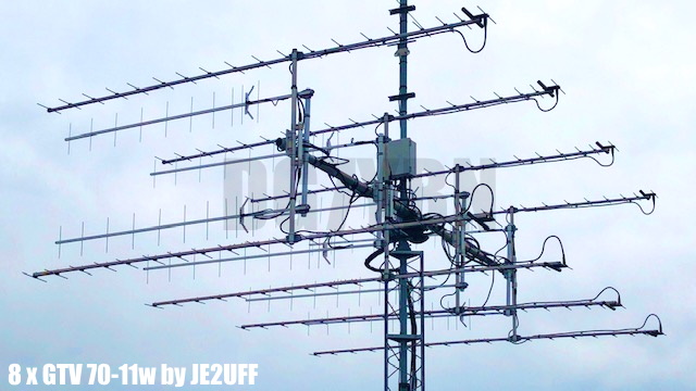
Photo Credit: JE2UFF. Tnx Toshi!
See making these Yagis in detail in Toshi's blog on 'digital-dxer.com'
4 x GTV 70-11w at JE2UFF June 2020

Photo Credit: JE2UFF. Tnx Toshi!
128 x GTV 70-11w, Folded Dipole version for Open Feedlines at DL7APV

These are built with 4 mm elements using my insulators, link to 7arrays.com
Read about the array here on DG7YBN.de
and also Bernds homepage with lots of detailed info and photos of the 128 Yagi array
GTV 70-11w portable version (4 parts boom) built by 7arrays (DG7YBN)

Using 50 W and this single, highly portable Yagi (4 boom sections) they did
8 QSOs, 8 initials, all JT65B, DXCC 7, WAC 2
Image: Dan, HB9CRQ
GTV 70-11w built by members of OM3KSI, Radioclub Leteckej fakulty

Image: OM3KSI
GTV 70-11w built by Wolfgang, DB5WB

Return Loss and VSWR Plot, click on chart to enlarge:
GTV 70-11w built by Thomas, M0ABA

2 x GTV 70-11w built by Kazuo, 7L1TIG

(operated with 20 .. 70 W and WSJT such a 2 x 1 m size array will clearly produce some results as QRPP EME station)
Kazou made a whole set of websites about DG7YBN 70 cm Yagis.
A very clear and methodic work. I recommend this to read. Use a free website online translator.
8 x GTV 70-11w built by Rob, PD7RKZ

See here for details
Photo: with kind permission of Rob, PD7RKZ
GTV 70-11w built by Thomas, M0ABA

Photo: with kind permission of Thomas, M0ABA
GTV 70-11w built by Sverker, SM7THS click on photo to enlarge

GTV 70-11w built by Igor, UA1019SWL


GTV 70-11w for portabel use operating satellites and QRPP EME built by Dragan, 4O4A


4 x GTV70-11w with folded dipole, built by Bernd, DL7APV
on 20 x 20 mm boom, 4 mm elements through boom and 6 mm dipole, see details below
4 Bay of GTV 70-11 Yagis with Open Feed Lines, sun noise up to 8.8 dB (at an sfi around 80)


Current distribution


Performance Data
Specs: with 8 mm elements @ 432.1 MHz
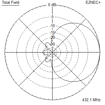
Gain vs. isotr. Rad.  15.0 dBi
Gain vs. Dipole       12.9 dBD
-3 dB E-plane         34.2 deg.
-3 dB H-plane         37.0 deg.
F/B                  -31.6 dB
F/R                  -27.9 dB
Impedance               50 ohms
Mechan. Length        2012 mm incl. 2 x 30 mm stand off
Electr. Length        2.81 λ

Stacking dist. h-pol.
top-to-bottom         1.09 m or 3.59 ft
side-by-side          1.18 m or 3.87 ft
How many OMs have been looking up this design?
Here is an add-on by the 'DXzone' web in which you may rate the GTV 70-11w design and its website.
|
Geometry

Ø8 mm Elements - On Boom - Dimensions (BC acc. DG7YBN)
Bent Dipole: DE(a) is the inner straight length and pos. on boom, DE(b) is position of tips and span width when bent
                  Refl   DE(b)   DE(a)   D1     D2     D3     D4     D5     D6     D7     D8     D9
Pos.                 0    85.8   104.5   150    246    428    651    902    1166   1439   1709   1952
NEC 1/2 ele.	 165.5	(161.7)  (33.5)	 153.5  151.5  146.0  142.5  140.0  138.5  136.5  132.5  129.0
"Ready to saw and drill" data for mounting elements on a 20 x 20 mm boom with BC according DG7YBN:
Actual BC for on a 20 x 20 mm Boom with standard insulators is 7.5 mm, SBC is 1.564 mm,
total length to add is ~ 9.06 mm
Sketch of bent dipole

Find a CAD Drawing of this Yagi with 8 mm elements & standard insulators on 20 x 20 mm boom in the download section

Geometry for 4 mm elements

The SBC is 1.56 mm. (Correction: D1 = 2 x 159 mm / 09.02.2015)
Using a large calliper gauge to control lenghts to the 10th of a millimeter is a must.
                  Refl   DE(b)   DE(a)   D1     D2     D3     D4     D5     D6     D7     D8     D9
Pos.                 0    87.0   104.5   150.5  245.5  428    651    902    1166   1439   1709   1952
NEC 1/2 ele.	 168.0	(163.2)  (33.5)	 159.0  156.0  151.0  147.75 146.0  144.25 142.5  138.75 135.75
Lengths ex. BC   336     326.4   (67.0)  318.0  312.0  302.0  295.5  292.0  288.5  285.0  277.5  271.5
Table 1: GTV 70-11w, 4 mm elements through boom 20 x 20 x 2 mm:
"Ready to saw and drill" data for mounting elements through boom with BC according SM5BSZ's BC.exe:
Note: with through Boom BC it is important to stick to the boom end offsets given below!
|
Boom shape: square Boom dim: 20 x 20 mm Wall thickn.: 2.0 mm Holes in boom: 6.0 mm Offset rear: 40 mm Offset front: 40 mm |
|

Note: This includes a "Segmentation Density Correction" (SBC) of 1.56 mm plus an offset of 0.70 mm per element = 2.26 mm
for compensation of the insulators (7arrays.com
Note: with through Boom BC it is important to stick to the boom end offsets given below!
Read abt. the SBC here
Same with 300 mm offset on rear boom end for effective formast mounting

Table 2: GTV 70-11w, 4 mm elements through boom 20 x 20 x 1.5 mm:
"Ready to saw and drill" data for mounting elements through boom with BC according SM5BSZ's BC.exe:
Note: with through Boom BC it is important to stick to the boom end offsets given below!
|
Boom shape: square Boom dim: 20 x 20 mm Wall thickn.: 1.5 mm Holes in boom: 6.0 mm Offset rear: 40 mm Offset front: 40 mm |
|
Table 3: GTV 70-11w, Same with 5/8 inch x 1.6 mm wall boom and 300 offset on rear boom end for effective formast mounting:

In the download section you find a CSV file for the Yagi Element Configuration Tool of this Yagi with 4 mm elements
with you can use for own adaptions to variations of boom dimensions etc.
For making of a 'Blade Dipole'
Radiation Pattern and VSWR Plots
Elevation and Azimuth plot at 432.1 MHz

SWR and Return Loss plots - simulated with 4nec2
Gain, F/B and F/R 431 to 434 MHz
Downloads
EZNEC file of this Yagi with Ø 8 mm ele.
CSV file for the Yagi Element Configuration Tool with 4 mm elements
CAD Drawing of this Yagi with 8 mm elements on 20 x 20 mm boom

GTV 70-11w with Folded Dipole

The straight split bent dipole can be replaced with a bent folded dipole like in any non-bent Yagi design.
In doing so the transformation ratio of 1:4 remains. The bent folded dipole versions impedance is 200 ohms.
The folded dipole itself is of Ø 6 mm; I recommend an 'elements through boom' built.
So that the folded dipole is centered in the element plane for best symmetry in the elevation pattern.
Geometry of the Folded Dipole
In the model we use the center of the tube, regardless of its actual diameter.
With this height is 44 mm, span width is 326 mm. Adding the real diameter of 6 mm we end up with
inner height = 38 mm, outer span width = 332 mm, see sketch


Note Folded Dipole mounting in plastic brackets compensation
Whatever plastic block is used to suspend or mount the dipoles wires will need to be compensated
by adding ~ 0.1 mm per millimeter of wire running in plastic. If you attach a 20 mm plastic block on top
of the boom to lead the dipoles upper wire a length of 2.0 mm / 2 = 1.0 mm needs to be added to the dipoles
span width. Assumed it runs free of contact to plastic on the down side.
We use factor 1/2 in a folded dipole then since it is a full wave loop.
Same applies to any BC if the wires run very close (~ < 3 mm) to the boom.
Folded dipoles for the GTV70-11w built by Rob, PD7RKZ
Dipoles bent to above dimensions, using a plastic dipole boxes sold by www.nuxcom.de
and 'smeared (all) well with Plast2000 in the boxes'.


Photo: with kind permission of Rob, PD7RKZ
Stacking
As on 432 MHz the Y-factor = T_earth / T_sky is so high, I see little chances to
improve an array's RX performance by using "Over Stacking" distances. However, depending on
the level of local QRM it might be worthwhile to try a decreased distance, especially in the H-plane.
Stacking Dist.    DL6WU Formula
H-plane               1.18 m
E-plane               1.09 m
A vertical 2 Yagi stack

Elevation plot and data of 2 Yagi bay using DL6WU stacking distances

Gain vs. isotr. Rad.  17.93 dBi
Gain vs. Dipole       15.78 dBD
-3 dB H-plane, appr.  40.8 deg.
-3 dB E-plane, appr.  16.8 deg.
F/B                  -32.1 dB
F/R                  -30.0 dB
T_ant                 --.- K*
G/T                   -.-- dB*
Theoretical numbers - these do not include phasing line losses
nor imperfections caused by H-frames or mast poles etc.
*) T_sky = 20 K, T_earth = 350 K as in VE7BQH G/T table
A 4 Yagi bay

Azimuth Plot (Elev. Plot see 2 x vert stack above)

Gain vs. isotr. Rad.  20.91 dBi
Gain vs. Dipole       18.76 dBD
-3 dB H-plane, appr.  15.4 deg.
-3 dB E-plane, appr.  16.8 deg.
F/B                  -31.5 dB
F/R                  -30.5 dB
T_ant                 32.8 K
G/T                   5.74 dB
3D pattern plot with 4nec2's 3D viewer

TANT screenshot

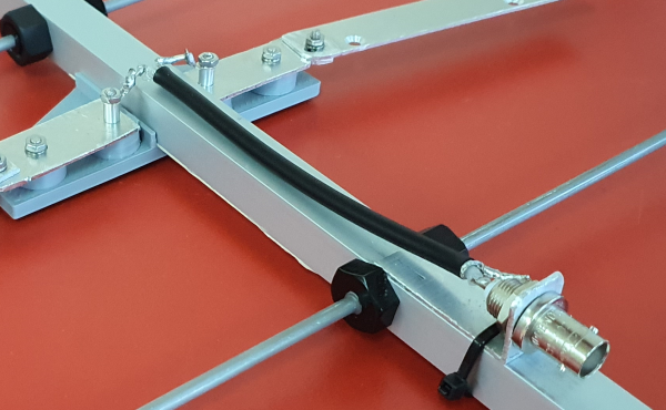
Symmetrising 50 to 50 ohms feedline to 432 MHz Bent DE
The principle is similar to the 1/4 Lambda coax. Adding 2 x 1/4 Lambda or a half wave line does not change anything but allows
to form a gentle bow below the boom or until behind the Reflector. Follow practical construction hints on "Building a Yagi" page.


 Attenzione!
Take care when lengthening the coax, measure the actual electrical length instead of considering v-factors specified in a catalogue only.
Attenzione!
Take care when lengthening the coax, measure the actual electrical length instead of considering v-factors specified in a catalogue only.A good choice may be the diam. 5 mm PTFE coax RG-142 B/U: real resonate length (432.2 MHz as 3/4 Lambda) shield-shield is around 348 mm
 Find more information on Phasing & Matching Lines page
 73, Hartmut, DG7YBN