-
• Main Page
- • Home
• Antennas - • 432 MHz
- YBN 70-5mA 0.5 m 432 MHz blue print of the YBN 2-5m 50 ohms high F/B direct feed 144 MHz Low Noise Yagi
3D Plot

- YBN 70-8zA 1.5 m high gain 28 ohms Yagi.
A design partly based on the hardware of the WY-7010, turning it into a 8 ele. 28 ohms Yagi with cleaner pattern, +1.8 dB gain and better VSWR.
Azimuth Plot
- YBN 70-14wzTune up your 19 ele. Tonna!
A design based on the hardware of the F9FT, turning it into a 14 ele. OWL with cleaner pattern, +0.3 dB gain and SWR less than 1.2 from 430 to 440 MHz
Azimuth Plot
- YBN 70-14+4wA 3.2 m very wideband 50 ohms Yagi with reflector wall that covers the whole 70 cm band with ease
Elevation Plot

- GTV 70-2wA 0.14 m GTV useful for portable operation and up to the satellit band and handheld activities of any kind
Elevation Plot

- GTV 70-3wA 0.21 m GTV useful for portable operation and up to the satellit band and lower noise stacks of any kind
Elevation Plot

- GTV 70-4mA 0.34 m GTV useful for portable operation up to the satellit band and lower noise stacks of any kind
Elevation Plot
- GTV 70-7wA 0.96 m GTV useful for portable operation up to the satellit band and lower noise stacks of any kind
Elevation Plot
- GTV 70-7nA 1.1 m 432 MHz blue print of the low impedance, yet 50 ohms direct feed 144 MHz Low Noise Yagi introduced in Dubus 1/2013
Elevation Plot
- GTV 70-8nA 1.3 m 432 MHz GTV with high gain but low backlobe volume. Makes a very compact 4 Yagi bay for QRP EME or contesting.
Elevation Plot
- GTV 70-9wA 1.44 m GTV ment to be useful as a vertical stack for contesting or be an ideal small size portable Yagi
Elevation Plot

- GTV 70-10wA 1.63 m GTV useful for portable operation up to the satellit band and lower noise stacks of any kind
Elevation Plot
- GTV 70-11wA 2.01 m GTV ment to be useful as a vertical stack for contesting or be an ideal small size portable Yagi or minimum size EME 4 bay
Elevation Plot
- GTV 70-13mA 2.5 m GTV ment to be useful as a vertical stack for contesting or be an ideal small size portable Yagi or minimum size EME 4 bay
Elevation Plot
- GTV 70-14m2.9 m version of the low impedance, yet 50 ohms direct feed Low Noise Yagi with bent DE introduced in Dubus 1/2013
Elevation Plot
- GTV 70-17m3.7 m version of the low impedance, yet 50 ohms direct feed Low Noise Yagi with bent DE introduced in Dubus 1/2013
Elevation Plot

- GTV 70-18w4.0 m version of the low impedance, yet 50 ohms direct feed Low Noise Yagi with bent DE introduced in Dubus 1/2013
Elevation Plot
- GTV 70-19m4.2 m version of the low impedance, yet 50 ohms direct feed Low Noise Yagi with bent DE introduced in Dubus 1/2013
Elevation Plot

- GTV 70-21n4.7 m version of the low impedance, yet 50 ohms direct feed Low Noise Yagi with bent DE introduced in Dubus 1/2013
Elevation Plot

- GTV 70-23m5.3 m version of the low impedance, yet 50 ohms direct feed Low Noise Yagi with bent DE introduced in Dubus 1/2013
Elevation Plot
- GTV 70-25m5.9 m version of the low impedance, yet 50 ohms direct feed Low Noise Yagi with bent DE introduced in Dubus 1/2013
Elevation Plot
- GTV 70-30m7.3 m version of the low impedance, yet 50 ohms direct feed Low Noise Yagi with bent DE introduced in Dubus 1/2013
Elevation Plot
- GTV 70-34w8.5 m version of the low impedance, yet 50 ohms direct feed Low Noise Yagi with bent DE introduced in Dubus 1/2013
Elevation Plot
- GTV 70-46w12.0 m version of the low impedance, yet 50 ohms direct feed Low Noise Yagi with bent DE introduced in Dubus 1/2013
Elevation Plot

- DL6WU YagisThe DL6WU Longyagi Series
Sample plot: 32 el. plus 4 x reflector
Elevation Plot

- YBN 70-5m
GTV 70-17m Yagi with bent Driven Element

EME + SSB to mid of band Longyagi
This Yagi has very low back lobes for its length. It may serve as single antenna for Tropo or make quiet 4 Yagi EME array.
It also makes a quiet contest antenna due to its very high F/B and clean rear pattern. The bent DE (K6STI style) transforms from approx. 17 ohms to 50 ohms at feed point.
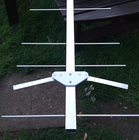
GTV 70-17m by GW4LWD

Photo Credit: GW4LWD
GTV 70-17m by 2M0ETJ

GTV 70-17m over a GTV 2-7n both built by Glyn, 2M0ETJ
GTV 70-17m by M0ABA ... this one enabled foundation license EME with 10 W


2017-12-02: M6 license holder M6EBQ does EME with 10 W out into a single GTV 70-17 element Yagi
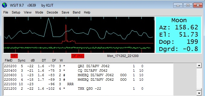
using but his (her) ten watt and a single Yagi.
M6 Licenses are restricted to 10 W out. We have seen an M6 EME contact before using a 4 bay of LFA Hybrid Yagis by Boban, YU7XL.
However this time a sole GTV 70-17n did the job. On the other side DL7APV, meanwhile equipped with 16 x 9 wl DJ9BV for h-pol
and 8 x GTV 70-11w for v-pol could even give a -22 dB report via WSJT giving "tnx QSO -22".
Congratulations to Dorothy, M6EBQ and Bernd, DL7APV ... and also Thomas, M0ABA for building the fine Yagi
And this QSO received at DG7YBN on single GTV 70-19m

Another first built by Thomas, M0ABA: GTV 70-17m ready for the ARRL EME Contest
Final Blade Dipole shape (on left) and adjustable experimenters blade to find the shape needed (on right), far right: simple elevation mount by M0ABA


How Thomas, M0ABA feeds these Yagis: self engineered coax hardline stub, the base plates are sawn from kitchen plastic boards(!)
A smart idea to access plastic sheets in the right thickness in small quantites at a reasonable price.


And this how the Yagi performs:
Breaking News ... MX0CNS <> EME QSO's PA2V and SM7THS
PA2V (4 x 27 ele. YU1CF Yagis) received at MX0CNS
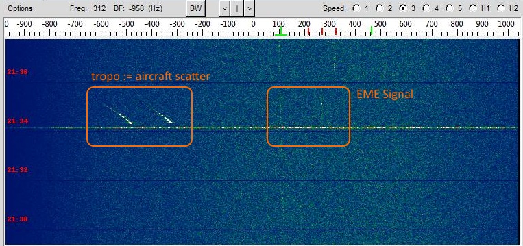
Note that the aricraft scattered signal appears but once and with the typical swing.


WSJT Screenshot QSO NC1I <> MX0CNS with GTV 70-17m and 60 W at Feed

 2017.11.03: DL7APV <> EME with single GTVV70-17m and just 10 W at feed


Current distribution

Performance Data
Specs: with 8 mm elements @ 432.1 MHz
Gain vs. isotr. Rad.  17.3 dBi
Gain vs. Dipole       15.1 dBD
-3 dB E-plane         26.6 deg.
-3 dB H-plane         27.8 deg.
F/B                  -38.3 dB
F/R                  -31.5 dB
Impedance               50 ohms
Mechan. Length        3628 mm
Electr. Length        5.23 λ

Stacking Dist. h-pol.
top-to-bottom         1.51 m   or  4.95 ft
side-by-side          1.44 m   or  4.74 ft
Geometry

The Drivers diameter is 10 mm for all examples.
Use EZNEC's Auto-Segmentation at 1050 MHz.
A simple symmetrising member may be made from a 3 x 1/4 Lambda line grounded at the far side with
N-flange-bushing and an aluminium plate and ferrite added as close as possible to the DE, see below.
How many OMs have been looking up this design?
Geometry for 8 mm elements

Using a large calliper gauge to control lenghts to the 10th of a millimeter is a must.
Geometry for 4 mm elements

"Ready to saw and drill" data for mounting elements through boom with BC according SM5BSZ's BC.exe:
Note: with through Boom BC it is important to stick to the boom end offsets given below!
|
This table is only valid for: Boom shape: square Boom dim: 1 x 1 inch Wall thickn.: 1/8 inch (3.175 mm) Holes in boom: 6.0 mm Offset rear: 40 mm Offset front: 40 mm |
|

Note: This includes a "Segmentation Density Correction" (SBC) of 0.90 mm plus an offset of 0.70 mm per element = 1.60 mm
for compensation of the insulators (7arrays.com
Note: Other insulators will need other offset, with their length being probably the most important parameter for this.
Thus I advise to cut other plastic insulators to 7 mm each to match at least the length of the pilot insulators.
Note: with through Boom BC it is important to stick to the boom end offsets given below!
Read abt. the SBC here

Using a large calliper gauge to control lenghts to the 10th of a millimeter is a must.
Pattern and VSWR Plots
Elevation and Azimuth plot at 432.1 MHz

SWR and Return Loss plots - simulated with 4nec2

Downloads
EZNEC file of this Yagi with 4 mm elements
EZNEC file of this Yagi with 8 mm elements
Stacking
As on the 432 MHz Band the Y-factor = T_earth / T_sky is that high I see little chances in
bettering an array's RX performance by using "Over Stacking" distances. However, depending
the level of local QRM it might be worthwhile to try less distance, especially in H-plane.
Stacking Dist.    DL6WU Formula
H-plane               1.44 m
E-plane               1.51 m
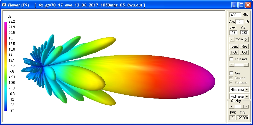
Elevation and azimuth plot and data of 4 Yagi bay using DL6WU stacking distances


AGTC_lite screenshot of this Yagi with 8 mm elements

Gain vs. isotr. Rad.  23.20 dBi
Gain vs. Dipole       21.05 dBD
F/B                   33.6 dB
F/R                   32.8 dB
T_ant                 28.5 K*
G/T                   8.65 dB*
Theoretical numbers, no phasing line losses
nor imperfections caused by H-frame included
*) T_sky = 20 K, T_earth = 350 K as in VE7BQH G/T table
Symmetrising 50 to 50 ohms Feedline to 432 MHz Bent DE
The principle is similar to the 1/4 Lambda coax. Adding 2 x 1/4 Lambda or a half wave line does not change anything but allows
to form a gentle bow below the boom or until behind the Reflector. Follow practical construction hints on "Building a Yagi" page.

 Attenzione!
Take care when lengthening the coax, measure the right length instead of refering to given v-factors only.
Attenzione!
Take care when lengthening the coax, measure the right length instead of refering to given v-factors only.A good choice may be the diam. 5 mm PTFE coax RG-142 B/U: real resonate length (432.2 Mhz as 3/4 Lambda) shield-shield is around 348 mm
 Find more information on Phasing & Matching Lines page
 73, Hartmut, DG7YBN