-
• Main Page
- • Home
• Antennas - • 432 MHz
- YBN 70-5mA 0.5 m 432 MHz blue print of the YBN 2-5m 50 ohms high F/B direct feed 144 MHz Low Noise Yagi
3D Plot

- YBN 70-8zA 1.5 m high gain 28 ohms Yagi.
A design partly based on the hardware of the WY-7010, turning it into a 8 ele. 28 ohms Yagi with cleaner pattern, +1.8 dB gain and better VSWR.
Azimuth Plot
- YBN 70-14wzTune up your 19 ele. Tonna!
A design based on the hardware of the F9FT, turning it into a 14 ele. OWL with cleaner pattern, +0.3 dB gain and SWR less than 1.2 from 430 to 440 MHz
Azimuth Plot
- YBN 70-14+4wA 3.2 m very wideband 50 ohms Yagi with reflector wall that covers the whole 70 cm band with ease
Elevation Plot

- GTV 70-2wA 0.14 m GTV useful for portable operation and up to the satellit band and handheld activities of any kind
Elevation Plot

- GTV 70-3wA 0.21 m GTV useful for portable operation and up to the satellit band and lower noise stacks of any kind
Elevation Plot

- GTV 70-4wA 0.33 m wideband GTV useful for portable operation up to the satellit band and lower noise stacks of any kind
Elevation Plot
- GTV 70-4mA 0.34 m GTV useful for portable operation up to the satellit band and lower noise stacks of any kind
Elevation Plot
- GTV 70-7wA 0.96 m GTV useful for portable operation up to the satellit band and lower noise stacks of any kind
Elevation Plot
- GTV 70-7nA 1.1 m 432 MHz blue print of the low impedance, yet 50 ohms direct feed 144 MHz Low Noise Yagi introduced in Dubus 1/2013
Elevation Plot
- GTV 70-8nA 1.3 m 432 MHz GTV with high gain but low backlobe volume. Makes a very compact 4 Yagi bay for QRP EME or contesting.
Elevation Plot
- GTV 70-9wA 1.44 m GTV ment to be useful as a vertical stack for contesting or be an ideal small size portable Yagi
Elevation Plot

- GTV 70-10wA 1.63 m GTV useful for portable operation up to the satellit band and lower noise stacks of any kind
Elevation Plot
- GTV 70-11wA 2.01 m GTV ment to be useful as a vertical stack for contesting or be an ideal small size portable Yagi or minimum size EME 4 bay
Elevation Plot
- GTV 70-13mA 2.5 m GTV ment to be useful as a vertical stack for contesting or be an ideal small size portable Yagi or minimum size EME 4 bay
Elevation Plot
- GTV 70-14m2.9 m version of the low impedance, yet 50 ohms direct feed Low Noise Yagi with bent DE introduced in Dubus 1/2013
Elevation Plot
- GTV 70-17m3.7 m version of the low impedance, yet 50 ohms direct feed Low Noise Yagi with bent DE introduced in Dubus 1/2013
Elevation Plot

- GTV 70-18w4.0 m version of the low impedance, yet 50 ohms direct feed Low Noise Yagi with bent DE introduced in Dubus 1/2013
Elevation Plot
- GTV 70-19m4.2 m version of the low impedance, yet 50 ohms direct feed Low Noise Yagi with bent DE introduced in Dubus 1/2013
Elevation Plot

- GTV 70-21n4.7 m version of the low impedance, yet 50 ohms direct feed Low Noise Yagi with bent DE introduced in Dubus 1/2013
Elevation Plot

- GTV 70-23m5.3 m version of the low impedance, yet 50 ohms direct feed Low Noise Yagi with bent DE introduced in Dubus 1/2013
Elevation Plot
- GTV 70-25m5.9 m version of the low impedance, yet 50 ohms direct feed Low Noise Yagi with bent DE introduced in Dubus 1/2013
Elevation Plot
- GTV 70-30m7.3 m version of the low impedance, yet 50 ohms direct feed Low Noise Yagi with bent DE introduced in Dubus 1/2013
Elevation Plot
- GTV 70-34w8.5 m version of the low impedance, yet 50 ohms direct feed Low Noise Yagi with bent DE introduced in Dubus 1/2013
Elevation Plot
- GTV 70-46w12.0 m version of the low impedance, yet 50 ohms direct feed Low Noise Yagi with bent DE introduced in Dubus 1/2013
Elevation Plot

- DL6WU YagisThe DL6WU Longyagi Series
Sample plot: 32 el. plus 4 x reflector
Elevation Plot

- YBN 70-5m
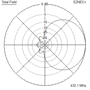
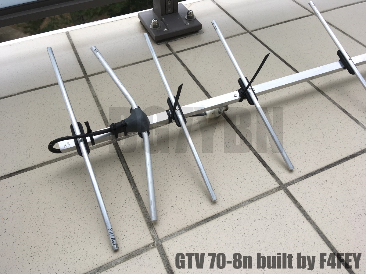
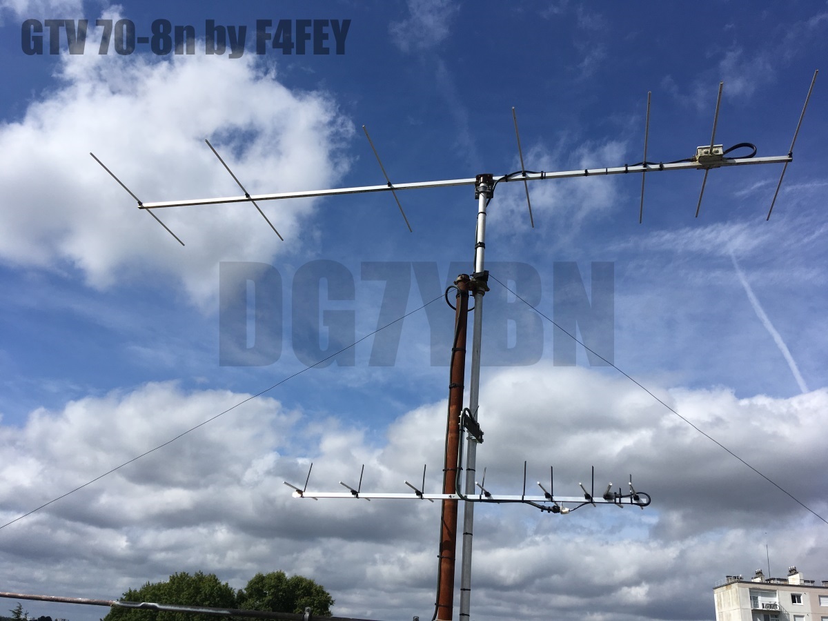
GTV 70-8n Yagi with bent Driven Element
EME + SSB narrow bandwidth version ... strictly G/T breeding
This Yagi has very low back lobes for its length. It may serve as single antenna for portable
use and certainly make a useful 4 x vertical stack. It makes a quiet contest antenna due to its
high F/B. The bent DE (K6STI style) transforms from approx. 17 ohms to 50 ohms at feed point.
 The GTV 70-8n is EME tested
GTV 70-8n built by Kazuo, 7L1TIG, see his website for details


GTV 70-8n built by Maxime, F4FEY


GTV 70-8n built and tested as EME proof in ARI contest by Thomas, M0ABA


And now here is screen shot of using the GTV 70-8n for all the smart critics that say 'ah ... thats just tropo':
NC1I (which is based stateside guys) received B-14 dB by MX0CNS (thats now in Europe guys).

And a WSJT screenshot by Thomas listening to QSO DL7APV - IK0IXO:
he reports very little noise (hence Low Noise Yagi ...), see the clean SpecJT screen. Mind this is EME
signal reception with a single small Yagi in daytime, with an ordinary preamp only.

Current distribution


Performance Data
Specs: with 4 mm elements @ 432.1 MHz
Gain vs. isotr. Rad.  13.6 dBi (13.62 dBi with 8 mm ele.)
Gain vs. Dipole       11.5 dBD
-3 dB E-plane         38.8 deg.
-3 dB H-plane         44.0 deg.
F/B                  -24.9 dB
F/R                  -27.9 dB
Impedance               50 ohms
Mechan. Length        1334 mm incl. 2 x 30 mm stand off
Electr. Length        1.84 λ

Stacking dist. h-pol.
top-to-bottom         0.93 m or 3.04 ft
side-by-side          1.04 m or 3.43 ft
How many OMs have been looking up this design?
Geometry

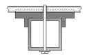
Table 1: GTV 70-8n, 8 mm elements on boom:
Dimensions using on-boom holders and BC acc. DG7YBN
            Refl      DE      D1      D2      D3      D4      D5      D6
Pos.           0      92     154.5   289     504     768    1034    1274
Ele.       330.3  (301.6)  306.4   298.7   288.8   280.8   274.4   263.3  <= ex. SBC and BC
Diam.          8      10       8       8       8       8       8       8

Total BC is SBC = 1.28 mm plus one of the following BC numbers
Standard Holders* 15 mm:  4.8 mm  (*) as sold by Konni, WiMo, Nuxcom, (7arrays 20 mm)
Standard Holders  20 mm:  7.5 mm
Standard Holders  25 mm: 11.5 mm
7arrays Holders   25 mm:  7.1 mm

Table 2: GTV 70-8n, 4 mm elements through boom:
"Ready to saw and drill" data for mounting elements through boom with BC according SM5BSZ's BC.exe:
Note: with through Boom BC it is important to stick to the boom end offsets given below!
Metric Boom 20 x 20 x 2 mm
|
Boom shape: square Boom dim: 20 x 20 mm Wall thickn.: 2.0 mm Holes in boom: 6.0 mm Offset rear: 300 mm Offset front: 40 mm |
|

Note: with through Boom BC it is important to stick to the boom end offsets given below!
With 300 mm offset on rear boom end for effective formast mounting

Imperial Boom 5-8"
|
Boom shape: square Boom dim: 5/8 x 5/8 inch Wall thickn.: 1.6 mm Holes in boom: 6.0 mm Offset rear: 300 mm Offset front: 40 mm |
|
Note: All the above include a "Segmentation Density Correction" (SBC) of 1.28 mm plus an offset of 0.70 mm per element = 1.98 mm
for compensation of the insulators (7arrays.com
Note: with through Boom BC it is important to stick to the boom end offsets given below!
Read abt. the SBC here

Same with 300 mm offset on rear boom end for effective formast mounting

In the download section you find a CSV file for the Yagi Element Configuration Tool of this Yagi with 4 mm elements
with you can use for own adaptions to variations of boom dimensions etc.
For making of a 'Blade Dipole'
Sketch of Bent Dipole

Radiation Pattern and VSWR Plots
Elevation and Azimuth plot at 432.1 MHz (4 mm ele.)


SWR and Return Loss plots - simulated with 4nec2
(I have settled the best Retrun Loss a bit higher for giving headroom in wet weather)

Gain, F/B and F/R 431 to 434 MHz

Downloads
EZNEC file of this Yagi with Ø 4 mm ele.
EZNEC file of a 4 Yagi Bay with Ø 4 mm ele.
EZNEC file of this Yagi with Ø 8 mm ele.
CSV file of this Yagi with Ø 4 mm ele. for the BC-Excel
Stacking
As on 432 MHz the Y-factor = T_earth / T_sky is so high, I see little chances to
improve an array's RX performance by using "Over Stacking" distances. However, depending on
the level of local QRM it might be worthwhile to try a decreased distance, especially in the H-plane.
Stacking Dist.    DL6WU Formula
H-plane               1.04 m
E-plane               0.93 m
A 4 Yagi bay

Elev. Plot

Az. Plot

Gain vs. isotr. Rad.  19.53 dBi
Gain vs. Dipole       17.38 dBD
-3 dB H-plane, appr.  17.4 deg.
-3 dB E-plane, appr.  19.8 deg.
F/B                  -28.9 dB
F/R                  -26.0 dB
T_ant                 41.9 K
G/T                   3.30 dB
3D pattern plot with 4nec2's 3D viewer


A Crossover between Diamond and Stagger Stacking
This stacking scheme is performed at stacking at DL6WU Distances plus 40 Percent
for both E and H plane.
Due to the larger stacking distances and hence a larger effective Aperture Area Diamond Stacking results in higher gain
at more modest side lobes with same Aperture Area used with the classical stacking scheme. However the rear lobes
grow as gain grows. I added Stagger Stacking as a proven tool to reduce the amount of rear lobes for arrays
formed of small Yagis.
Note that the mid pair of Yagis must be feed with a phase lag of 90 degrees by using
feedlines that are 0.25 wave length longer than the ones for the upper and lower Yagi.
Stacking Dist.    DL6WU Formula x 1.40
H-plane               1.46 m
E-plane               1.30 m
mid Yagis in x        171 mm

Find a link to more information about Stagger Stacking down the page.
 Attenzione! Attenzione! |
Viewing and judging Patterns of Diamond Stacks by Azimuth and Elevation Plots leads to wrong conclusions according their amount of front-, side- and rear lobes suppression. As the Diamond Stackings wave interference pattern runs the most characteristic lobes by a 45 degree shift to the ordinary stacking scheme. So they do not show in the ordinary Azimuth and Elevation plots. Which is the reason why many rumors about the marvels of Diamond Stacking are to be heared. Hence I show a 3D plot here. |
The above is the reason why I implemented Stagger Stacking into the Diamond Stacking, as that usually
decreases rear lobes by a signifcant amount. And so it does in practise here.

Antenna Temperature and G/T produced with beta version of AGTC by F5FOD


with full open source code. Background of the AGTC is scheduled to be published in Dubus 1/2017
Antenna Temperature and G/T produced with TANT

Read more about Stagger Stacking and feeding such arrays here
Symmetrising 50 to 50 ohms feedline to 432 MHz Bent DE
The principle is similar to the 1/4 Lambda coax. Adding 2 x 1/4 Lambda or a half wave line does not change anything but allows
to form a gentle bow below the boom or until behind the Reflector. Follow practical construction hints on "Building a Yagi" page.


Attenzione!
Take care when lengthening the coax, measure the actual electrical length instead of considering v-factors specified in a catalogue only.A good choice may be the diam. 5 mm PTFE coax RG-142 B/U: real resonate length (432.2 MHz as 3/4 Lambda) shield-shield is around 348 mm
 Find more information on Phasing & Matching Lines page
 73, Hartmut, DG7YBN