-
• Main Page
- • Home
• Antennas - • 432 MHz
- YBN 70-5mA 0.5 m 432 MHz blue print of the YBN 2-5m 50 ohms high F/B direct feed 144 MHz Low Noise Yagi
3D Plot

- YBN 70-8zA 1.5 m high gain 28 ohms Yagi.
A design partly based on the hardware of the WY-7010, turning it into a 8 ele. 28 ohms Yagi with cleaner pattern, +1.8 dB gain and better VSWR.
Azimuth Plot
- YBN 70-14wzTune up your 19 ele. Tonna!
A design based on the hardware of the F9FT, turning it into a 14 ele. OWL with cleaner pattern, +0.3 dB gain and SWR less than 1.2 from 430 to 440 MHz
Azimuth Plot
- YBN 70-14+4wA 3.2 m very wideband 50 ohms Yagi with reflector wall that covers the whole 70 cm band with ease
Elevation Plot

- GTV 70-2wA 0.14 m GTV useful for portable operation and up to the satellit band and handheld activities of any kind
Elevation Plot

- GTV 70-3wA 0.21 m GTV useful for portable operation and up to the satellit band and lower noise stacks of any kind
Elevation Plot

- GTV 70-4wA 0.33 m wideband GTV useful for portable operation up to the satellit band and lower noise stacks of any kind
Elevation Plot
- GTV 70-4mA 0.34 m GTV useful for portable operation up to the satellit band and lower noise stacks of any kind
Elevation Plot
- GTV 70-7wA 0.96 m GTV useful for portable operation up to the satellit band and lower noise stacks of any kind
Elevation Plot
- GTV 70-7nA 1.1 m 432 MHz blue print of the low impedance, yet 50 ohms direct feed 144 MHz Low Noise Yagi introduced in Dubus 1/2013
Elevation Plot
- GTV 70-8nA 1.3 m 432 MHz GTV with high gain but low backlobe volume. Makes a very compact 4 Yagi bay for QRP EME or contesting.
Elevation Plot
- GTV 70-9wA 1.44 m GTV ment to be useful as a vertical stack for contesting or be an ideal small size portable Yagi
Elevation Plot

- GTV 70-10wA 1.63 m GTV useful for portable operation up to the satellit band and lower noise stacks of any kind
Elevation Plot
- GTV 70-11wA 2.01 m GTV ment to be useful as a vertical stack for contesting or be an ideal small size portable Yagi or minimum size EME 4 bay
Elevation Plot
- GTV 70-13mA 2.5 m GTV ment to be useful as a vertical stack for contesting or be an ideal small size portable Yagi or minimum size EME 4 bay
Elevation Plot
- GTV 70-14m2.9 m version of the low impedance, yet 50 ohms direct feed Low Noise Yagi with bent DE introduced in Dubus 1/2013
Elevation Plot
- GTV 70-17m3.7 m version of the low impedance, yet 50 ohms direct feed Low Noise Yagi with bent DE introduced in Dubus 1/2013
Elevation Plot

- GTV 70-18w4.0 m version of the low impedance, yet 50 ohms direct feed Low Noise Yagi with bent DE introduced in Dubus 1/2013
Elevation Plot
- GTV 70-19m4.2 m version of the low impedance, yet 50 ohms direct feed Low Noise Yagi with bent DE introduced in Dubus 1/2013
Elevation Plot

- GTV 70-21n4.7 m version of the low impedance, yet 50 ohms direct feed Low Noise Yagi with bent DE introduced in Dubus 1/2013
Elevation Plot

- GTV 70-23m5.3 m version of the low impedance, yet 50 ohms direct feed Low Noise Yagi with bent DE introduced in Dubus 1/2013
Elevation Plot
- GTV 70-25m5.9 m version of the low impedance, yet 50 ohms direct feed Low Noise Yagi with bent DE introduced in Dubus 1/2013
Elevation Plot
- GTV 70-30m7.3 m version of the low impedance, yet 50 ohms direct feed Low Noise Yagi with bent DE introduced in Dubus 1/2013
Elevation Plot
- GTV 70-34w8.5 m version of the low impedance, yet 50 ohms direct feed Low Noise Yagi with bent DE introduced in Dubus 1/2013
Elevation Plot
- GTV 70-46w12.0 m version of the low impedance, yet 50 ohms direct feed Low Noise Yagi with bent DE introduced in Dubus 1/2013
Elevation Plot

- DL6WU YagisThe DL6WU Longyagi Series
Sample plot: 32 el. plus 4 x reflector
Elevation Plot

- YBN 70-5m
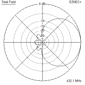
GTV 70-2m Yagi with bent Driven Element
EME + SSB band, usable up to 440 MHz, relatively clean rear pattern version
This little Yagi has a high F/B for a 2 ele., which makes it quite useful for lower noise
or weaker signal operations. The bent DE (K6STI style) transforms from approx. 40 ohms to
50 ohms at feed point.
 The GTV 70-2m is the worlds tiniest Yagi that did EME QSOs
GTV 70-2m built by Kazuo, 7L1TIG, see his website for details

"Public Notice":
We frequently find unqualified comments like on 'Reddit' placed by Disbelievers in a tiny 2 element Yagi moon bounce contact. Which in a way is understandable. With the link budget in path loss in dB given it took a miracle, a super big gun and several months of testing to complete this < 260 w EIRP EME QSO. The miracle was the Nov. 2016 Super Moon, which was closest to earth moon since 1948.
Of coarse everyone is free to question statements and superlatives in todays world. Especially if read on the internet. Which actually attests a healthy attitude of thinking. But please be serious in your arguments. Do not disqualify yourself by suggesting this QSO was a terrestrial contact without the most qualified EME radio operators noticing. Be assured that EME operators in close distance to one another face what you suggest as possible terrestrial contact as ever day challenge with really near by other EME stations. With that the traces in the waterfall diagram of the WSJT software look completly different and also the travelling time to and back from the moon is missing the 2 second delay. This check is routine for any only half experiences EME operator and easy and plain to spot.
Suggesting the chances for a terrestrial contact JO01JM (MX0CNS) to JO62JR = 929 km (DL7APV) or to JN47CG = 714 km (HB9Q) is a vague theory. Do you have an idea how much down in dB the spill over of such a dish pointed skywards is? Or what remarkable super tropo conditions would have had to be to allow a terrestrial contact at all? Even with antennas facing each other over such a distance? You might consider taking a look at a signal sent from across the atlantic: NC1I received at MX0CNS on a 8 el. 70 cm Yagi. Pretty much not a chance for a tropo signal this time ... .
Ready about this in full on the GTV 70-8n website.
.
Ready about this in full on the GTV 70-8n website.
Since the 8th of September 2018 the 2 el. Yagi QRPP EME is yesterdays news. MX0CNS did it with just the bent dipole and 60 w. Which leaves us with an EIRP of less 120 W on the QRPP station side. While on the far end the new 128 x GTV 70-11w array of DL7APV, replacing the 16 x DJ9BV Longyagis used for all the other records, did a superb job picking the weak signal with its 36 dBi gain.
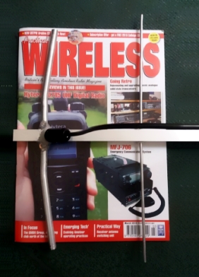
Well, I see you are not satisfied with my explanations?
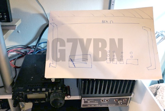
Ok then, I give in. First of all MX0CNS used a hidden Beko linear amplifier. Here it is:
• Check out the MX0CNS facebook for news and details We frequently find unqualified comments like on 'Reddit' placed by Disbelievers in a tiny 2 element Yagi moon bounce contact. Which in a way is understandable. With the link budget in path loss in dB given it took a miracle, a super big gun and several months of testing to complete this < 260 w EIRP EME QSO. The miracle was the Nov. 2016 Super Moon, which was closest to earth moon since 1948.
Of coarse everyone is free to question statements and superlatives in todays world. Especially if read on the internet. Which actually attests a healthy attitude of thinking. But please be serious in your arguments. Do not disqualify yourself by suggesting this QSO was a terrestrial contact without the most qualified EME radio operators noticing. Be assured that EME operators in close distance to one another face what you suggest as possible terrestrial contact as ever day challenge with really near by other EME stations. With that the traces in the waterfall diagram of the WSJT software look completly different and also the travelling time to and back from the moon is missing the 2 second delay. This check is routine for any only half experiences EME operator and easy and plain to spot.

Suggesting the chances for a terrestrial contact JO01JM (MX0CNS) to JO62JR = 929 km (DL7APV) or to JN47CG = 714 km (HB9Q) is a vague theory. Do you have an idea how much down in dB the spill over of such a dish pointed skywards is? Or what remarkable super tropo conditions would have had to be to allow a terrestrial contact at all? Even with antennas facing each other over such a distance? You might consider taking a look at a signal sent from across the atlantic: NC1I received at MX0CNS on a 8 el. 70 cm Yagi. Pretty much not a chance for a tropo signal this time ...
 .
Ready about this in full on the GTV 70-8n website.
.
Ready about this in full on the GTV 70-8n website.
Since the 8th of September 2018 the 2 el. Yagi QRPP EME is yesterdays news. MX0CNS did it with just the bent dipole and 60 w. Which leaves us with an EIRP of less 120 W on the QRPP station side. While on the far end the new 128 x GTV 70-11w array of DL7APV, replacing the 16 x DJ9BV Longyagis used for all the other records, did a superb job picking the weak signal with its 36 dBi gain.
Well, I see you are not satisfied with my explanations?
Ok then, I give in. First of all MX0CNS used a hidden Beko linear amplifier. Here it is:
'Operation Odyssey' accomplished
NEW WORLD RECORD: 2 ele. GTV and less 260 W EIRP -
2016-11-11: 18-10 UTC - HB9Q and MX0CNS complete a QSO
after 7 months of testing, with B-19 dB at MX0CNS, see WSJT screenshot at MX0CNS

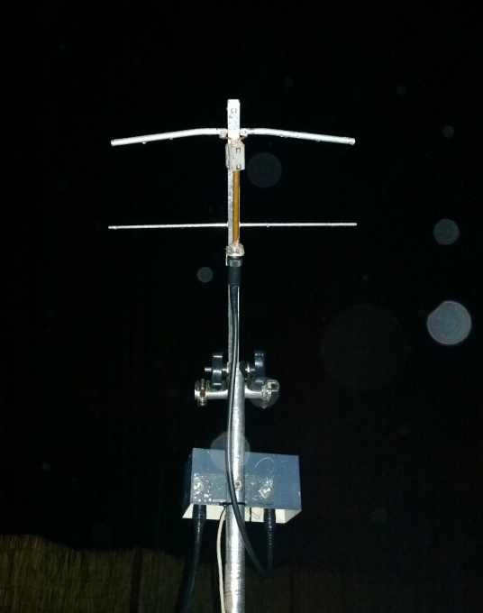
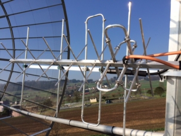
GTV70-2m at MX0CNS a short time after the QSO was completed

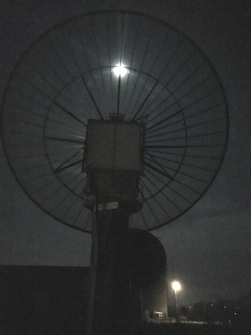
HB9Q's dish same time, photo on courtesy of Dan, HB9Q

xpol LFA dish feed, photo on courtesy of Justin, G0KSC
HB9Q's equipment: Dish Ø15.3 m, xpol LFA feed, LNA 0.42 dB, 1 kW SSPA, TR432H transverter, Zeus SDR, IQ+u rev. B (HB9DRI),
and SM5BSZ's Linrad. The decodes on the HB9Q side were as follows, (tnx Dan!):
MAP65: 91 -270 105 180300 2.1 -28 HB9Q MX0CNS JO01 0 17 110 V WSJT 10, 90�: 180300 3 -26 2.8 728 3 * HB9Q MX0CNS JO01 0 10 180700 5 -28 715 4 RO 180900 4 -29 710 3 73 WSJT X, -135�: 180300 0 -27 2.9 728 3 * HB9Q MX0CNS JO01 0 6 180500 0 -33 1.9 747 15 180700 4 -29 715 2 RO 180900 0 -33 1.9 731 50
2016-11-13: 18-48 UTC - DL7APV and MX0CNS complete a QSO
with B-28 dB at DL7APV and see screenshot from MX0CNS / M0ABA below
A video of the MX0CNS - DL7APV QSO with this tiny Yagi
by Thomas, M0ABA at MX0CNS. External link to Youtube here
A video of HB9Q received up to -22 dB during the 2016 ARRL EME Contest on this tiny Yagi
by Thomas, M0ABA at MX0CNS. External link to Youtube here
A GTV 70-2m built and measured by Kazuo, 7L1TIG. Link to his website in Japanese here

Retrospect: A special call for operations and support:
After success with the GTV70-4m and -3w, the 'Operation Wavelet' Thomas, M0ABA @ MX0CNS goes for one more:
Please help us to make this real, MX0CNS is open for skeds, also with the larger 7 and 4 ele. Yagis
M0ABA @ MX0CNS runs 'Operation Odyssey' to find the real bottom line
Can a 70 cm EME QSO be done with this handful of aluminium and 60 W at feedpoint = 260 W EIRP only?Please help us to make this real, MX0CNS is open for skeds, also with the larger 7 and 4 ele. Yagis
M0ABA can be contacted for skeds via Essex Dx Group - Facebook

Nasa's Apollo 13's Command Module (CMS-109) was named 'Odyssey'. It was launched Apr. 11th, 1970.
The 13ths mission of the Apollo Program did not make it to a landing on the moon due to a serious failure in an oxygen tank
switching valve. Which let that service module based tank explode. Just when entering the moons orbit in a distance of more
than 300,000 k from mother earth. �Houston, we�ve had a problem here� - listen to the full radio communication audio
But the way the astronauts of this mission handled the life threatening situation and made it home safely against many odds is
maybe more impressive than actual lunar landing missions. So we decided to tribute this operation to the crew of Apollo 13
and name it 'Operation Odyssey'.
Almost breakthrough:
2016-11-11: 20-00 UTC - HB9Q receives MX0CNS with 60 W at feed:
and sends 'OOO' ... just the final '73' did not get thru. DL7APV and UA3PTW also received the tiny signal!
More decodes with real sleeve quarterwave stub
The used before thin coax 3 x 1/4 λ symmetrising coax was measured as too
long by DG7YBN. Thus Thomas, M0ABA designed and build this sleeve tube using AppCAD by Agilent.
2016-07-01: 07-50 UTC - This is HB9Q received at MX0CNS:

On time for the 46th anniversary of the safe return of the men of Apollo 13 ...
Operation Odyssey manages first decodes despite the moon being in its apogee ..
2016-04-16: 22-50 UTC - This is DL7APV received at MX0CNS:
DL7APV received MX0CNS as well. With up to -25 dB but no decodes on that.
|
GTV70-2m - 4nec2's 3D viewer Can this Yagi do Earth-Moon-Earth? |
Photo: Nasa Project Apollo Archive These antennas make it half way ... Moon-Earth |

3D Radation Pattern ... and GTV 70-2m built by Thomas, M0ABA: see how TINY it is ...

This website has been viewed by how many 70 cm enthusiasts since Apr. 2016?
Performance Data
                     Elem. 4 mm
Gain vs. isotr. Rad.   6.3 dBi
Gain vs. Dipole        4.2 dBD
-3 dB E-plane         58.4 deg.
-3 dB H-plane         136 deg.
F/B                  -10.6 dB
F/R                   -6.1 dB
Impedance               50 ohms
Mechan. Length         134 mm
Electr. Length        0.19 λ
An EME Record Replica ...

Geometry
The 4 mm elements are ment for an 'elements through boom' built.
Segmentation BC and Base BC (see BC page) must be added.
A simple symmetrising member may be made from a 3 x 1/4 Lambda line grounded at the far side with
N-flange-bushing and an aluminium plate and ferrite added as close as possible to the DE, see below.

        Pos.    Full Length      1/2 Length
                                   in NEC

Refl.     0.0      336.0           168.0
DE(b)   115.0      293.0        33.5-146.5
DE(a)   134.0       67.0          0-33.5

                 ele. 4 mm       ele. 4 mm
The Drivers diameter is 10 mm for all examples.
Use EZNEC's Auto-Segmentation at 1050 MHz.
For the SBC the frequency impact is 433.4 MHz - 432.2 MHz = 1.1 MHz
Multiplication with the 70 cm correction factor of 0.92 mm/MHz results in 1.1 mm to add to the common BC.
Using the proposed through boom insulators add a fixed offset on to BC of 0.7 mm so that total SBC = 1.8 mm
• "Ready to saw and drill" data for mounting 4.0 mm elements insulated through boom with SM5BSZ's BC.exe applied
Note that with an elements insulated through boom built for best results boomlength and positions to first /last element must be kept as given.
Because the position of an element relative to its nearer boom end is a serious parameter in the BC.exe.
This table is only valid for:
Boom shape: square
Boom dim: 5/8 in x 5/8 in (15.9 mm)
Wall thickn.: 1.6 mm
Holes in boom: 6.0 mm
Offset rear: 300 mm
Offset front: 40 mm
• Data set for 4 mm elements with rear boom end offset = 300 mm for formast mounting

Sketch of Bent Dipole

Pattern and VSWR Plots
Elevation and Azimuth plot at 432.1 MHz

Simulated RL and SWR plot 430 ... 440 MHz

VNA measured RL and SWR plot 420 ... 440 MHz

Downloads
EZNEC file of this Yagi with Ø 4 mm elements
Symmetrising 50 to 50 ohms Feedline to 432 MHz Bent DE
The principle is similar to the 1/4 Lambda coax. Adding 2 x 1/4 Lambda or a half wave line does not change anything but allows
to form a gentle bow below the boom or until behind the Reflector. Follow practical construction hints on "Building a Yagi" page.

 Attenzione!
Take care when lengthening the coax, measure the right length instead of refering to given v-factors only.
Attenzione!
Take care when lengthening the coax, measure the right length instead of refering to given v-factors only.A good choice may be the diam. 5 mm PTFE coax RG-142 B/U: real resonate length (432.2 Mhz as 3/4 Lambda) shield-shield is around 348 mm
 Find more information on Phasing & Matching Lines page
 73, Hartmut, DG7YBN