-
• Main Page
- • Home
• Antennas - • 432 MHz
- YBN 70-5mA 0.5 m 432 MHz blue print of the YBN 2-5m 50 ohms high F/B direct feed 144 MHz Low Noise Yagi
3D Plot

- YBN 70-8zA 1.5 m high gain 28 ohms Yagi.
A design partly based on the hardware of the WY-7010, turning it into a 8 ele. 28 ohms Yagi with cleaner pattern, +1.8 dB gain and better VSWR.
Azimuth Plot
- YBN 70-14wzTune up your 19 ele. Tonna!
A design based on the hardware of the F9FT, turning it into a 14 ele. OWL with cleaner pattern, +0.3 dB gain and SWR less than 1.2 from 430 to 440 MHz
Azimuth Plot
- YBN 70-14+4wA 3.2 m very wideband 50 ohms Yagi with reflector wall that covers the whole 70 cm band with ease
Elevation Plot

- GTV 70-2wA 0.14 m GTV useful for portable operation and up to the satellit band and handheld activities of any kind
Elevation Plot

- GTV 70-3wA 0.21 m GTV useful for portable operation and up to the satellit band and lower noise stacks of any kind
Elevation Plot

- GTV 70-4mA 0.34 m GTV useful for portable operation up to the satellit band and lower noise stacks of any kind
Elevation Plot
- GTV 70-7wA 0.96 m GTV useful for portable operation up to the satellit band and lower noise stacks of any kind
Elevation Plot
- GTV 70-7nA 1.1 m 432 MHz blue print of the low impedance, yet 50 ohms direct feed 144 MHz Low Noise Yagi introduced in Dubus 1/2013
Elevation Plot
- GTV 70-8nA 1.3 m 432 MHz GTV with high gain but low backlobe volume. Makes a very compact 4 Yagi bay for QRP EME or contesting.
Elevation Plot
- GTV 70-9wA 1.44 m GTV ment to be useful as a vertical stack for contesting or be an ideal small size portable Yagi
Elevation Plot

- GTV 70-10wA 1.63 m GTV useful for portable operation up to the satellit band and lower noise stacks of any kind
Elevation Plot
- GTV 70-11wA 2.01 m GTV ment to be useful as a vertical stack for contesting or be an ideal small size portable Yagi or minimum size EME 4 bay
Elevation Plot
- GTV 70-13mA 2.5 m GTV ment to be useful as a vertical stack for contesting or be an ideal small size portable Yagi or minimum size EME 4 bay
Elevation Plot
- GTV 70-14m2.9 m version of the low impedance, yet 50 ohms direct feed Low Noise Yagi with bent DE introduced in Dubus 1/2013
Elevation Plot
- GTV 70-17m3.7 m version of the low impedance, yet 50 ohms direct feed Low Noise Yagi with bent DE introduced in Dubus 1/2013
Elevation Plot

- GTV 70-18w4.0 m version of the low impedance, yet 50 ohms direct feed Low Noise Yagi with bent DE introduced in Dubus 1/2013
Elevation Plot
- GTV 70-19m4.2 m version of the low impedance, yet 50 ohms direct feed Low Noise Yagi with bent DE introduced in Dubus 1/2013
Elevation Plot

- GTV 70-21n4.7 m version of the low impedance, yet 50 ohms direct feed Low Noise Yagi with bent DE introduced in Dubus 1/2013
Elevation Plot

- GTV 70-23m5.3 m version of the low impedance, yet 50 ohms direct feed Low Noise Yagi with bent DE introduced in Dubus 1/2013
Elevation Plot
- GTV 70-25m5.9 m version of the low impedance, yet 50 ohms direct feed Low Noise Yagi with bent DE introduced in Dubus 1/2013
Elevation Plot
- GTV 70-30m7.3 m version of the low impedance, yet 50 ohms direct feed Low Noise Yagi with bent DE introduced in Dubus 1/2013
Elevation Plot
- GTV 70-34w8.5 m version of the low impedance, yet 50 ohms direct feed Low Noise Yagi with bent DE introduced in Dubus 1/2013
Elevation Plot
- GTV 70-46w12.0 m version of the low impedance, yet 50 ohms direct feed Low Noise Yagi with bent DE introduced in Dubus 1/2013
Elevation Plot

- DL6WU YagisThe DL6WU Longyagi Series
Sample plot: 32 el. plus 4 x reflector
Elevation Plot

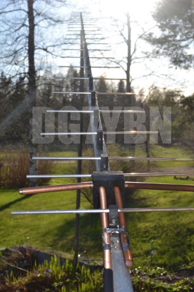
- YBN 70-5m
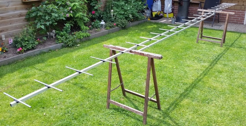
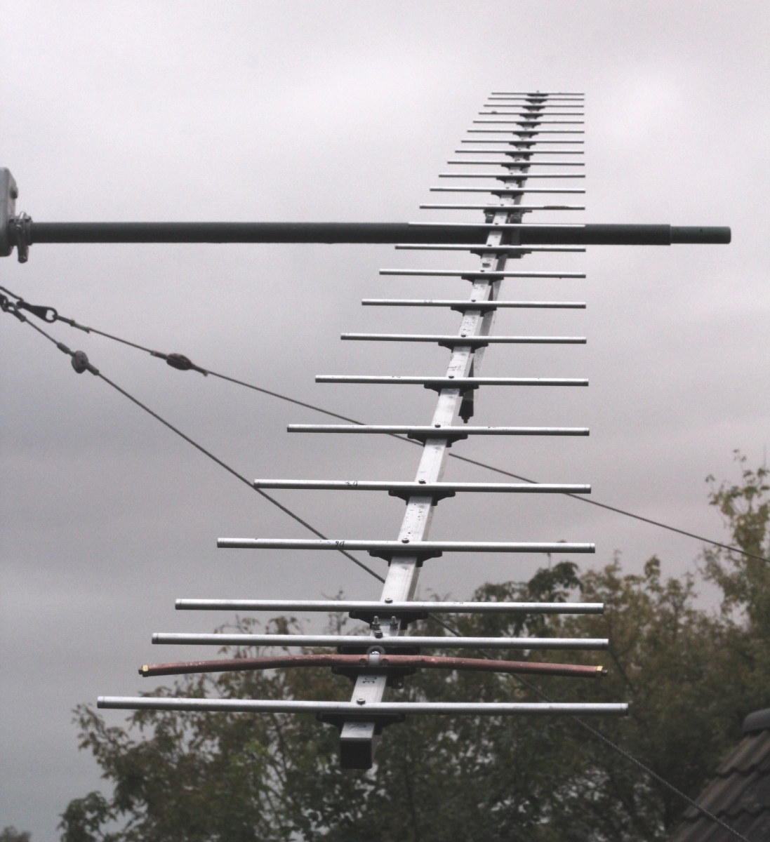
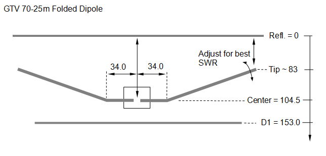
GTV 70-25m Yagi with bent Driven Element
EME + SSB band version
This Yagi has very low back lobes for its length. It may serve as single antenna for Tropo or even EME.
A 4 Yagi bay will make an excellent EME array. It also makes a quiet contest antenna due to its high F/B.
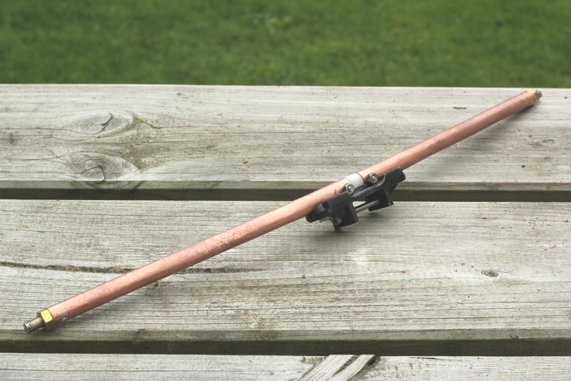
The bent DE (K6STI style) transforms from approx. 17 ohms to 50 ohms at feed point.
8 x GTV 70-25m 'The Rainmaker' built by ZS6JON for ZS4TX


Since 26th of December 2022 we have a new 432 MHz DX World Record with an array of GTV 70-25m Yagis:
Band   Call 1    Loc 1     Call 2   Loc 2      Mode    Prop.  Date[d-m-y]  QRB[km]
432    ZS4TX     KG30BX    NH6Y     BL10TS     Q65B    EME    2022-12-26   19054
see www.ok2kkw.com/dxrecords.htm
Screenshots of the QSO on NH6Y side:
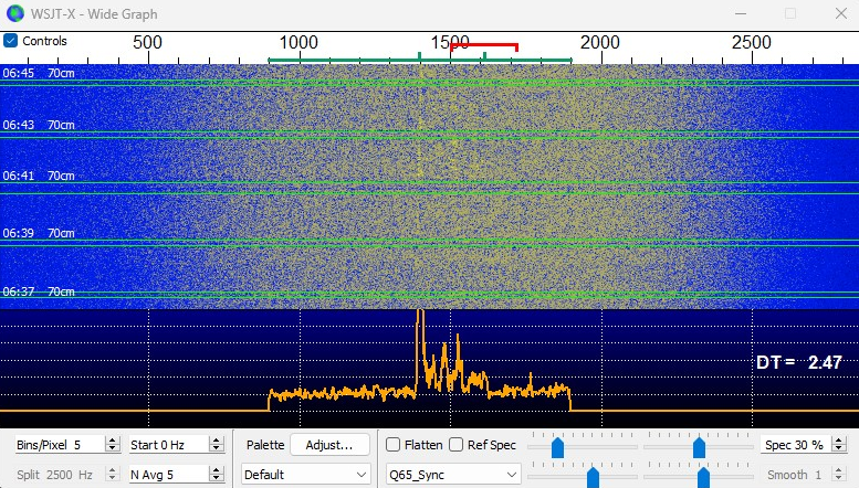
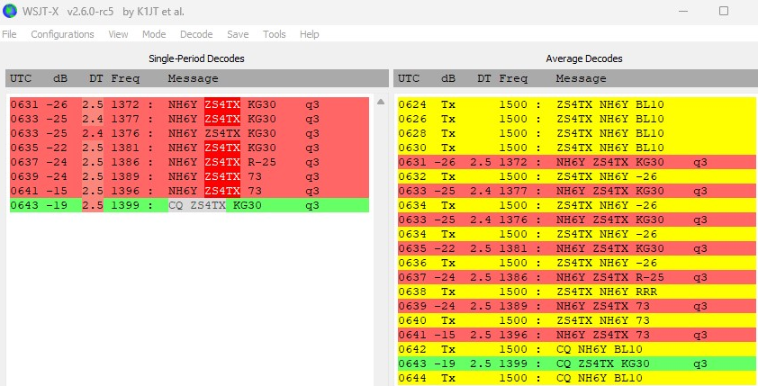
His last CQ at ZS4TX was still decoded at almost -1 degree of Moon elevation at NH6Y.
NH6Y has a 'negative horizon' to the West and can see the ocean clearly from his station
• NH6Y Station Info:
Tom operated 2 x 25 hpol K1FO Yagis, 600 W Tajfun 1000 brick, Q5 transverter and WD5ADO LNA.
Screenshots of the QSO on ZS4TX side:
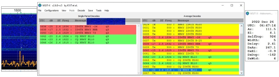
• ZS4TX Station Info:
Bernie operated this array, Icom IC-910H, 750 W out, Microham Digi Keyer II, LNAs built by ZS6JON.
8 x GTV 70-25m built by Sverker, SM7THS
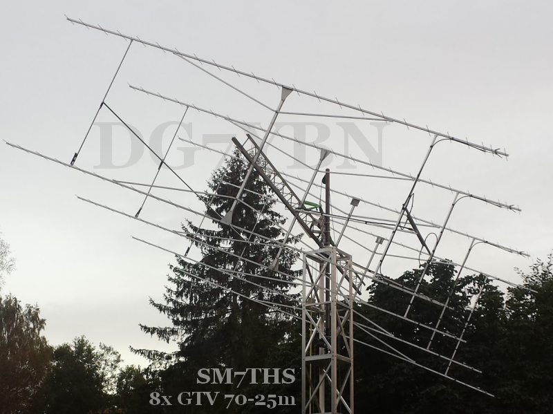

These Yagis are built on 20 x 20 mm boom with 4 mm elements. The blade dipole shape is close to the drawing
on the GTV 70-19 website but made from t = 1 mm which seems to require a little more bending angle.
SM7THS reports own echos from the moon at -6.3 dB using 400 W out with this array of 8 Yagis.
And reading DG7YBN with single GTV 70-19 and 270 W out off the moon at -23 dB :-). On 2nd of Dec.2017
his blog reads good propagations, own echos -3.5 dB, HB9Q rxed at -1 dB, an SSB QSO with DF3RU and
a single Yagi 250 W station worked.
2 x GTV 70-25m built by Sverker, SM7THS
SM7THS used the 2 GTVs, 600W and LNA with an NF of approx. 0.34dB.
Read his report from 2016 Oct. ARRL 1st leg EME contest with that equipment:
"During the contest I worked in total 31 QSO's and a few stations with similar setups like KA1GT and
LU8ENU. Outside the contest the smallest station worked so far was SM7GVF with a single yagi and 1KW
Hrd my own echoes at strongest -12.6 dB in JT echo mode."

GTV 70-25m h-pol. with added GTV 70-14m v-pol. "The Rainmaker" built by Sverker, SM7THS
Test setup for finding out if both planes are working as simulated.

Take a look at Sverkers QRZ.com
and Sverkers blog abt. building 8 x GTV 70-25 and GTV 70-14 ...
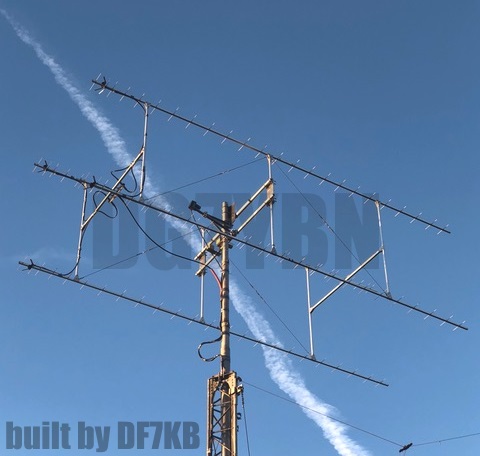
4 x GTV 70-25m built by Wolf, DF7KB built on 25 x 25 mm booms using 4 mm elements
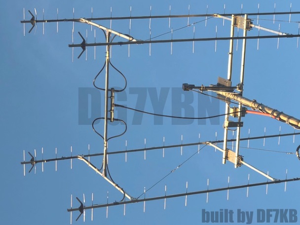

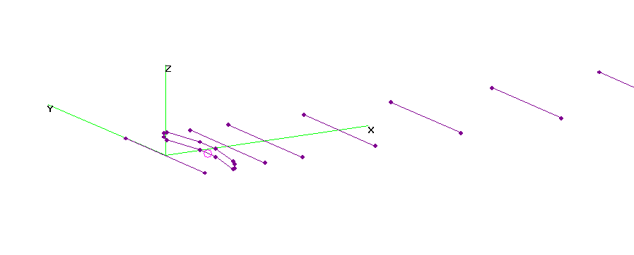
Current distribution
GTV 70-25m "The Rainmaker" by John, ZS6JON

and has a GTV70-14m in v-plane installed in its front part
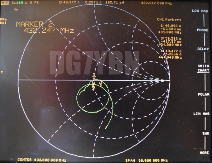
and Return Loss plotted with calibrated coax on an Anritsu MS2000 VNA

And Jukka at OH3TR, Tampere University of Technology / Tampereen tekkarien radiokerho
fed with 1/2 inch coax and solid symmetrising stub.
GTV 70-25m at PA2CV, Alex

And 2016-10-16 on right: First test as EME novice with 100 W out, instantly an almost QSO with PI9CAM due to much drift in trx.

Slideshow: Ingenious bent dipole for the GTV 70-25m by Alex, PA2CV. 8 mm soft copper tube with brass screws in the tips
Performance Data
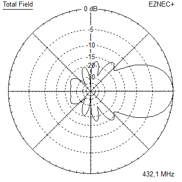
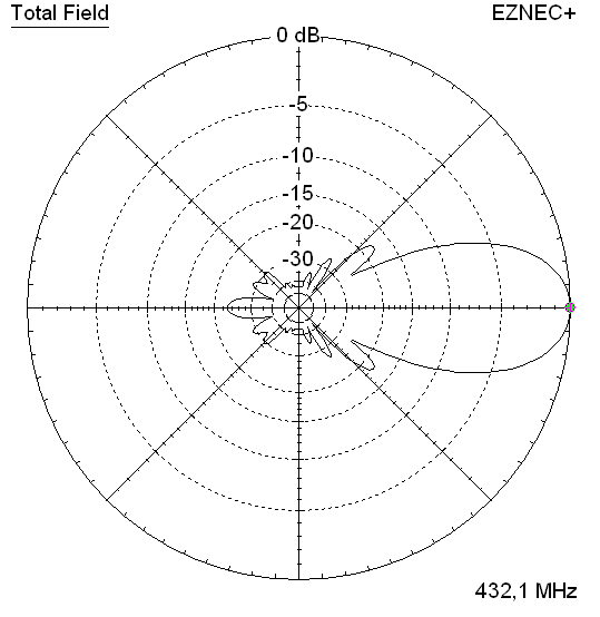
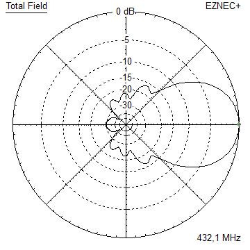
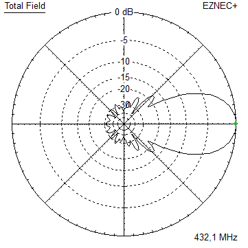
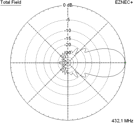
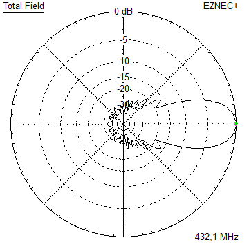
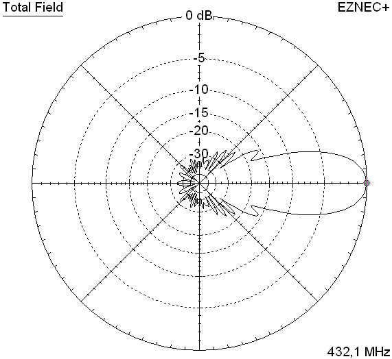
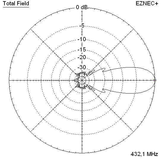
Gain vs. isotr. Rad.  18.9 dBi (4 mm elements and low segmentation)
Gain vs. Dipole       16.8 dBD
-3 dB E-plane         22.2 deg.
-3 dB H-plane         22.8 deg.
F/B                  -36.9 dB
F/R                  -34.0 dB
Impedance               50 ohms
Mechan. Length        5820 mm
Electr. Length        8.39 λ

Stacking Dist. h-pol.
top-to-bottom         1.76 m
side-by-side          1.80 m
Geometry
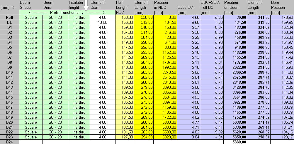
EZNEC wire table for Ø 4 mm elements

Geometry for thin elements through boom

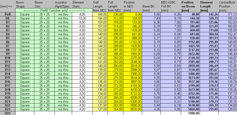
Table 1: GTV 70-25m, 4 mm elements through a 20 x 20 mm boom:
"Ready to saw and drill" data for mounting elements through boom with BC according SM5BSZ's BC.exe:
Note: with through Boom BC it is important to stick to the boom end offsets given below!
|
This table is only valid for: Boom shape: square Boom dim: 20 x 20 mm Wall thickn.: 2.0 mm Holes in boom: 6.0 mm Offset rear: 30 mm Offset front: 30 mm |
|

Insulators by 7arrays.com
Using a large calliper gauge to control lenghts to the 10th of a millimeter is a must.
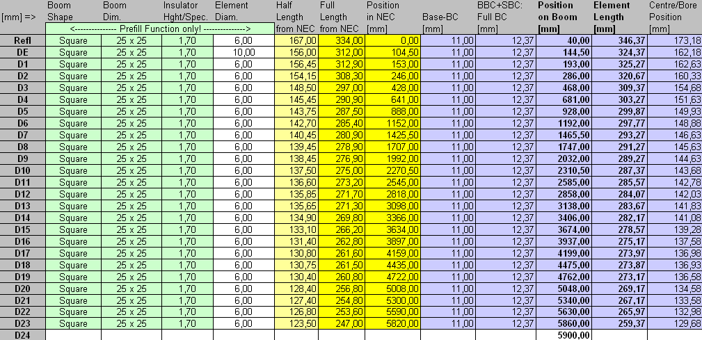
Table 2: GTV 70-25m, 4 mm elements through a 25 x 25 mm boom:
"Ready to saw and drill" data for mounting elements through boom with BC according SM5BSZ's BC.exe:
Note: with through Boom BC it is important to stick to the boom end offsets given below!
|
This table is only valid for: Boom shape: square Boom dim: 25 x 25 mm Wall thickn.: 2.0 mm Holes in boom: 6.0 mm Offset rear: 40 mm Offset front: 40 mm |
|
Insulators by 7arrays.com
Using a large calliper gauge to control lenghts to the 10th of a millimeter is a must.
Table 3: GTV 70-25m, 3/16 inch elements through boom:
"Ready to saw and drill" data for mounting elements through boom with BC according SM5BSZ's BC.exe:
Note: with through Boom BC it is important to stick to the boom end offsets given below!
This table is only valid for:
Boom shape: square
Boom dim: 25 x 25 mm
Wall thickn.: 1.6 mm
Holes in boom: 7.9 mm
Offset rear: 40 mm
Offset front: 40 mm
SBC is: 1.37 mm plus 0.7 mm for compensation for 432 MHz and insulator of length 7 mm
<= NEC Geometry 3/16 inch ele. insulated through boom incl. SM5BSZ BC.exe Correction

Using a large calliper gauge to control lenghts to the 10th of a millimeter is a must.
Table 4: GTV 70-25m, 8 mm elements semi insulated on boom with standard holders:
 <= NEC Geometry 8 mm ele. semi insulated on boom incl. DG7YBN BC and an SBC of 1.37 mm
• On boom 20 x 20 mm with 8 mm elements

• On boom 25 x 25 mm with 6 mm elements
The Drivers diameter is 10 mm for all examples.
Use EZNEC's Auto-Segmentation at 1050 MHz.
A simple symmetrising member may be made from a 3 x 1/4 Lambda line grounded at the far side with
N-flange-bushing and an aluminium plate and ferrite added as close as possible to the DE, see below.
Sketch of Bent Dipole

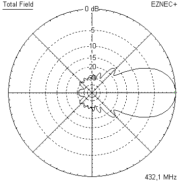
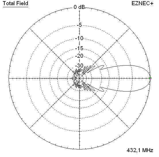
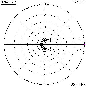
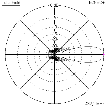
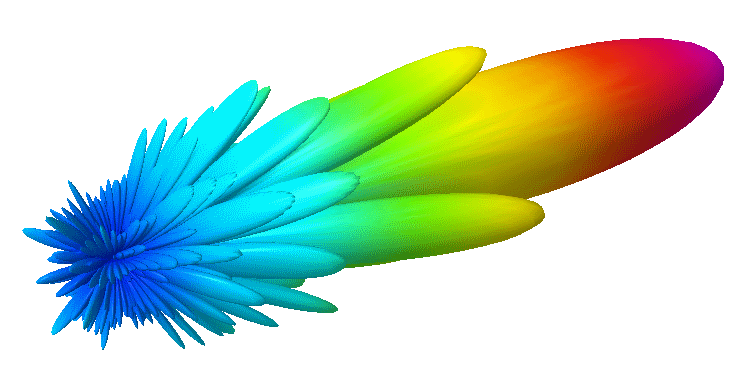
Pattern and VSWR Plots
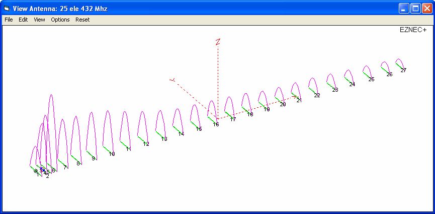
Elevation and Azimuth plot at 432.1 MHz

SWR and Return Loss plots - simulated with 4nec2
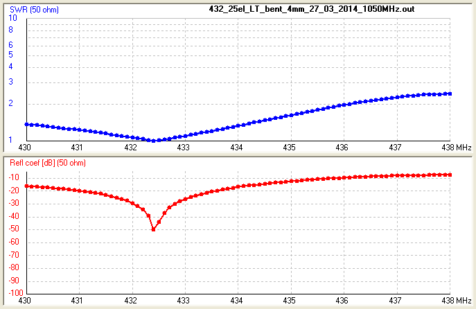
Return Loss plot - PA2CV's build: 430.0 to 435.0 MHz (tnx Alex!)

Downloads
EZNEC file of this Yagi with 4 mm elements
EZNEC file of this Yagi with 3/16 inch elements
EZNEC file of this Yagi with 8 mm elements
GTV 70-25m with Folded Dipole
The straight split bent dipole can be replaced with a bent folded dipole like in any non-bent Yagi design.
In doing so the transformation ratio of 1:4 remains. The bent folded dipole versions impedance is 200 ohms.
The folded dipole itself is of Ø 6 mm; I recommend an 'elements through boom' built.
So that the folded dipole is centered in the element plane for best symmetry in the elevation pattern.
Geometry of the Folded Dipole
In the model we use the center of the tube, regardless of its actual diameter.
With this NEC model height is 44 mm, span width is 308 mm. Adding the real diameter of 6 mm we end up with
inner height = 38 mm, outer span width = 314 mm, see sketch
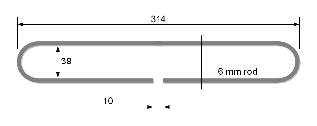
Note Folded Dipole mounting in plastic brackets compensation
Whatever plastic block is used to suspend or mount the dipoles wires will need to be compensated
by adding ~ 0.1 mm per millimeter of wire running in plastic. If you attach a 20 mm plastic block on top
of the boom to lead the dipoles upper wire a length of 2.0 mm / 2 = 1.0 mm needs to be added to the dipoles
span width. Assumed it runs free of contact to plastic on the down side.
We use factor 1/2 in a folded dipole then since it is a full wave loop.
Same applies to any BC if the wires run very close (~ < 3 mm) to the boom.
SWR and Return Loss plots - simulated with 4nec2

Stacking
As on the 432 MHz Band the Y-factor = T_earth / T_sky is that high I see little chances in
bettering an array's RX performance by using "Over Stacking" distances. However, depending
the level of local QRM it might be worthwhile to try less distance, especially in H-plane.
Stacking Dist.    DL6WU Formula
top-to-bottom         1.76 m
side-by-side          1.80 m
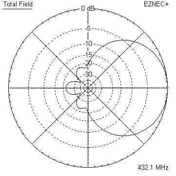
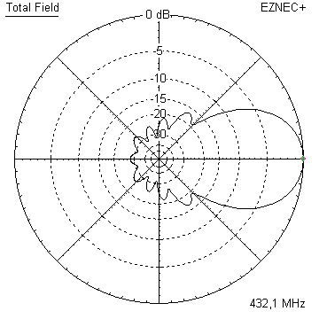
Azimuth plot and data of 4 Yagi bay using DL6WU stacking distances
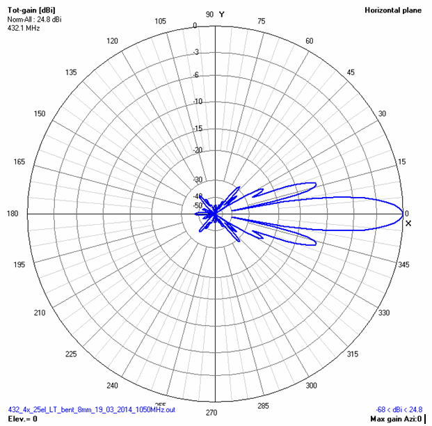
Gain vs. isotr. Rad.  24.84 dBi
Gain vs. Dipole       22.69 dBD

T_ant                 26.4 K*
G/T                  10.63 dB*

Theoretical numbers, no phasing line losses
nor imperfections caused by H-frame included
*) T_sky = 20 K, T_earth = 350 K as in VE7BQH G/T table

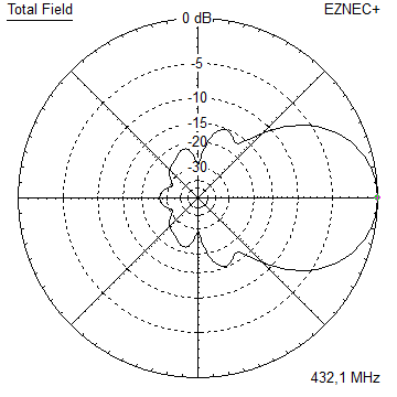
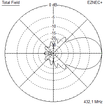
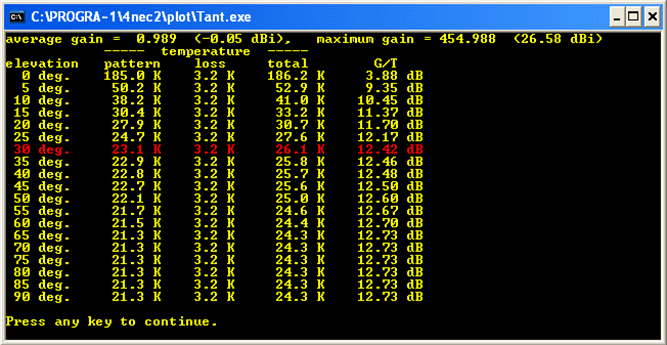
Elevation plot and data of 6 Yagi bay using DL6WU stacking distances
Gain vs. isotr. Rad.  26.58 dBi
Gain vs. Dipole       24.43 dBD

T_ant                 26.1 K*
G/T                  12.42 dB*

Theoretical numbers, no phasing line losses
nor imperfections caused by H-frame included
*) T_sky = 20 K, T_earth = 350 K as in VE7BQH G/T table
Symmetrising 50 to 50 ohms Feedline to 432 MHz Bent DE
The principle is similar to the 1/4 Lambda coax. Adding 2 x 1/4 Lambda or a half wave line does not change anything but allows
to form a gentle bow below the boom or until behind the Reflector. Follow practical construction hints on "Building a Yagi" page.

 Attenzione!
Take care when lengthening the coax, measure the right length instead of refering to given v-factors only.
Attenzione!
Take care when lengthening the coax, measure the right length instead of refering to given v-factors only.A good choice may be the diam. 5 mm PTFE coax RG-142 B/U: real resonate length (432.2 Mhz as 3/4 Lambda) shield-shield is around 348 mm
 Find more information on Phasing & Matching Lines page
 73, Hartmut, DG7YBN