-
• Main Page
- • Home
• Antennas - • 432 MHz
- YBN 70-5mA 0.5 m 432 MHz blue print of the YBN 2-5m 50 ohms high F/B direct feed 144 MHz Low Noise Yagi
3D Plot

- YBN 70-8zA 1.5 m high gain 28 ohms Yagi.
A design partly based on the hardware of the WY-7010, turning it into a 8 ele. 28 ohms Yagi with cleaner pattern, +1.8 dB gain and better VSWR.
Azimuth Plot
- YBN 70-14wzTune up your 19 ele. Tonna!
A design based on the hardware of the F9FT, turning it into a 14 ele. OWL with cleaner pattern, +0.3 dB gain and SWR less than 1.2 from 430 to 440 MHz
Azimuth Plot
- YBN 70-14+4wA 3.2 m very wideband 50 ohms Yagi with reflector wall that covers the whole 70 cm band with ease
Elevation Plot

- GTV 70-2wA 0.14 m GTV useful for portable operation and up to the satellit band and handheld activities of any kind
Elevation Plot

- GTV 70-3wA 0.21 m GTV useful for portable operation and up to the satellit band and lower noise stacks of any kind
Elevation Plot

- GTV 70-4wA 0.33 m wideband GTV useful for portable operation up to the satellit band and lower noise stacks of any kind
Elevation Plot
- GTV 70-4mA 0.34 m GTV useful for portable operation up to the satellit band and lower noise stacks of any kind
Elevation Plot
- GTV 70-7wA 0.96 m GTV useful for portable operation up to the satellit band and lower noise stacks of any kind
Elevation Plot
- GTV 70-7nA 1.1 m 432 MHz blue print of the low impedance, yet 50 ohms direct feed 144 MHz Low Noise Yagi introduced in Dubus 1/2013
Elevation Plot
- GTV 70-8nA 1.3 m 432 MHz GTV with high gain but low backlobe volume. Makes a very compact 4 Yagi bay for QRP EME or contesting.
Elevation Plot
- GTV 70-9wA 1.44 m GTV ment to be useful as a vertical stack for contesting or be an ideal small size portable Yagi
Elevation Plot

- GTV 70-10wA 1.63 m GTV useful for portable operation up to the satellit band and lower noise stacks of any kind
Elevation Plot
- GTV 70-11wA 2.01 m GTV ment to be useful as a vertical stack for contesting or be an ideal small size portable Yagi or minimum size EME 4 bay
Elevation Plot
- GTV 70-13mA 2.5 m GTV ment to be useful as a vertical stack for contesting or be an ideal small size portable Yagi or minimum size EME 4 bay
Elevation Plot
- GTV 70-14m2.9 m version of the low impedance, yet 50 ohms direct feed Low Noise Yagi with bent DE introduced in Dubus 1/2013
Elevation Plot
- GTV 70-17m3.7 m version of the low impedance, yet 50 ohms direct feed Low Noise Yagi with bent DE introduced in Dubus 1/2013
Elevation Plot

- GTV 70-18w4.0 m version of the low impedance, yet 50 ohms direct feed Low Noise Yagi with bent DE introduced in Dubus 1/2013
Elevation Plot
- GTV 70-19m4.2 m version of the low impedance, yet 50 ohms direct feed Low Noise Yagi with bent DE introduced in Dubus 1/2013
Elevation Plot

- GTV 70-21n4.7 m version of the low impedance, yet 50 ohms direct feed Low Noise Yagi with bent DE introduced in Dubus 1/2013
Elevation Plot

- GTV 70-23m5.3 m version of the low impedance, yet 50 ohms direct feed Low Noise Yagi with bent DE introduced in Dubus 1/2013
Elevation Plot
- GTV 70-25m5.9 m version of the low impedance, yet 50 ohms direct feed Low Noise Yagi with bent DE introduced in Dubus 1/2013
Elevation Plot
- GTV 70-30m7.3 m version of the low impedance, yet 50 ohms direct feed Low Noise Yagi with bent DE introduced in Dubus 1/2013
Elevation Plot
- GTV 70-34w8.5 m version of the low impedance, yet 50 ohms direct feed Low Noise Yagi with bent DE introduced in Dubus 1/2013
Elevation Plot
- GTV 70-46w12.0 m version of the low impedance, yet 50 ohms direct feed Low Noise Yagi with bent DE introduced in Dubus 1/2013
Elevation Plot

- DL6WU YagisThe DL6WU Longyagi Series
Sample plot: 32 el. plus 4 x reflector
Elevation Plot

- YBN 70-5m
GTV 70-10w Yagi with bent Driven Element
From EME to SAT operation frequency up to 436 MHz with VSWR < 1:1.2
A Satellite version GTV 70-10w SAT centered at 435,5 MHz is shown down the page.
For this design I put a bit of emphasis on good ability to make it an XPOL Yagi.
Which means a driver cell that is "open" enough to fit the second plane's elements
into but keep dipoles and D1 nicely separated per plane.
Hence this Yagi is suitable to make a nice Cross Yagi
This Yagi has very low back lobes for its length. It may serve as single antenna for portable
use and certainly make a useful 4 x vertical stack. It makes a quiet contest antenna due to its
high F/B. The bent DE (K6STI style) transforms from approx. 17 ohms to 50 ohms at feed point.
GTV 70-10w xpol SAT by ZS6JON

upright bent dipole from 1/2 inch strip, new 3D printed holder.
GTV 70-10w xpol SAT by VK5LO at minikits.com.au

For details see xpol section of this website and full description on the minikits website
Photo credit: Mark, VK5LO (tnx Mark!)
GTV 70-10w by M0ABA

Current distribution

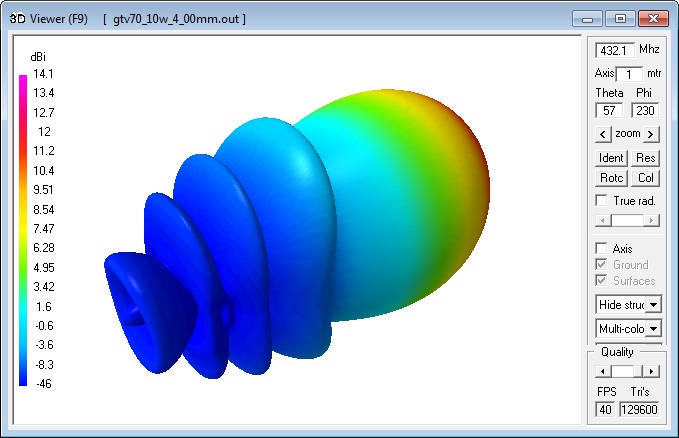
Performance Data
Specs: with 4 mm elements @ 432.1 MHz
Gain vs. isotr. Rad.  14.1 dBi
Gain vs. Dipole       11.9 dBD
-3 dB E-plane         37.4 deg.
-3 dB H-plane         41.4 deg.
F/B                  -28.6 dB
F/R                  -24.3 dB
Impedance               50 ohms
Mechan. Length        1632 mm incl. 2 x 40 mm stand off
Electr. Length        2.24 λ

Stacking dist. h-pol.
top-to-bottom         0.98 m or 3.22 ft
side-by-side          1.08 m or 3.55 ft
How many OMs have been looking up this design?
Geometry
Bent Dipole: DE(a) is the inner straight length and pos. on boom, DE(b) is position of tips and span width when bent

|
• Drawing of the blade dipole as PDF, • The Dipole of the GTV 70-9w fits the GTV 70-10w nicely (tnx Thomas, M0ABA for measuring this!) |
|

The model uses EZNEC's Auto-Segmentation at 1050 MHz.
The DE's is 10 mm for all examples.
Using a 'Blade Dipole' is recommended with elements through boom
A simple symmetrising section may be made from a 3 x 1/4 Lambda line grounded at the far end with
N-flange-bushing and an aluminium plate and ferrite core added as close as possible to the DE,
see below.

Metric Ø4 mm Elements - Through Boom - Dimensions (BC acc. SM5BSZ's BC.exe)
"Ready to saw and drill" data for mounting elements through boom with BC according SM5BSZ's BC.exe:
Note: with through Boom BC it is important to stick to the boom end offsets given below!
Table 1: Metric Boom 20 x 20 x 2 mm
|
Boom shape: square Boom dim: 20 x 20 mm Wall thickn.: 2.0 mm Holes in boom: 6.0 mm Offset rear: 40 mm Offset front: 40 mm |
|


Table 2: Metric Boom 20 x 20 x 2 mm, formast mount
|
Boom shape: square Boom dim: 20 x 20 mm Wall thickn.: 2.0 mm Holes in boom: 6.0 mm Offset rear: 300 mm Offset front: 40 mm |
|

Table 3: 4.76 mm = 3/16 inch El., Imperial Boom 1 x 1 inch x 1.6 mm, formast mount
|
Boom shape: square Boom dim: 1 x 1 in Wall thickn.: 2.0 mm Holes in boom: 6.0 mm Offset rear: 300 mm Offset front: 40 mm |
This Yagi with 8 mm elements on a 20 x 20 mm boom with standard insulators for formast mounting (rear offset 400 mm)

|
Ele. 8.0 mm DE 10.0 mm Boom 20 x 20 mm |
|

"Ready to saw and drill" data for mounting elements on boom with BC according DG7YBN for standard insulators
as sold by WiMo, Tino's Funkshop, HF-Kits NL, 7arrays:
You may alter the rear offset as long as you keep a minimum of 40 mm, it will not influence an 'on boom' BC.

Building hints:
For building hints see the GTV 70-19
For fastening elements through boom
For making of a 'Blade Dipole'
Radiation Pattern and VSWR Plots
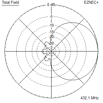
Elevation and Azimuth plot at 432.1 MHz

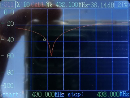
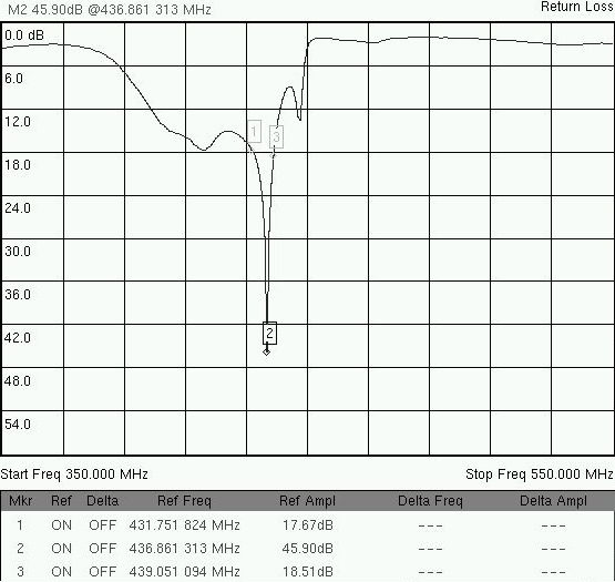
VSWR and Return Loss (S11)


Return Loss and VSWR Plots by Thomas, M0ABA: -36 dB resp. 1:1.006 at 432.1 MHz

Return Loss and VSWR Plots by John, ZS6JON for the Sat XPOL version 436.5 MHz

GTV 70-10w XPOL
The xpol versions are planned with a large rear boom offset for adding a counterpoise
Radiation Pattern of SAT Version ... 435.5 MHz, Elevation and Azimuth Pattern

• GTV 70-10w EME xpol: 432 MHz Version
EME xpol version: Antenna view in EZNEC

• Geometry:
Table 1: 4.00 mm El., Metric Boom 25 x 25 x 2 mm, formast mount
"Ready to saw and drill" data for mounting elements through boom with BC according SM5BSZ's BC.exe:
|
This table is only valid for: Boom shape: square Boom dim: 25 x 25 mm Wall thickn.: 2.0 mm Holes in boom: 6.0 mm h-plane: Offset rear: 740 mm Offset front: 320 mm v-plane: Offset rear: 1020 mm Offset front: 40 mm |
|
Note: This does include an SBC of 1.28 mm plus a correction for the insulators (v-factor!) of 0.7 mm
for compensation of the insulators (7arrays.com
Note: with through Boom BC it is important to stick to the boom end offsets given below!
v-plane

h-plane

Table 2: 4.76 mm = 3/16 inch El., Imperial Boom 1 x 1 inch x 1.6 mm, formast mount
|
This table is only valid for: Boom shape: square Boom dim: 1 x 1 in Wall thickn.: 1.6 mm Holes in boom: 7.5 mm h-plane: Offset rear: 740 mm Offset front: 320 mm v-plane: Offset rear: 1020 mm Offset front: 40 mm |
v-plane
![]()
h-plane
![]()
On Boom:
Table 1: GTV 70-10w xpol SAT (435.5 MHz)
with 6.35 mm = 1/4 inch elements, boom 20 x 20 mm, formast mount
|
This table is only valid for: Boom shape: square Boom dim: 20 x 20 mm Stauff Clamps: 106-4-PP h-plane: Offset rear: 740 mm Offset front: 320 mm v-plane: Offset rear: 1020 mm Offset front: 40 mm |
|

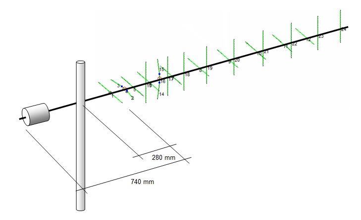
• GTV 70-10w SAT xpol: 435 MHz Version
SAT xpol version:
Offset between h- and v-plane is 280 mm or 146.4 deg. phase at 435.5 MHz
VSWR Source1: h-plane
VSWR Source2: v-plane

Table 1 SAT 435 MHz xpol: 6,35 mm = 1/4 inch El., Metric Boom 20 x 20 mm (also 3/4 inch), Formast Mount
|
This table is only valid for: Boom shape: square Boom dim: 20 x 20 mm Offset rear: 720 mm Offset front: 320 mm v-plane: Offset rear: 1020 mm Offset front: 40 mm |
Stauff Light Series Type: LB-106-PP

v-plane

h-plane

Table 2: SAT 435 MHz xpol: 8.0 mm El., Metric Boom 20 x 20 mm, Formast Mount
|
This table is only valid for: Boom shape: square Boom dim: 20 x 20 mm Offset rear: 720 mm Offset front: 320 mm v-plane: Offset rear: 1020 mm Offset front: 40 mm |
|

Offset between h- and v-plane is 280 mm or 146.4 deg. phase at 435.5 MHz

Table 3: 4.76 mm = 3/16 inch El. through a Boom 1 x 1 inch x 1.6 mm, formast mount
|
This table is only valid for: Boom shape: square Boom dim: 1 x 1 in Wall thickn.: 1.6 mm Holes in boom: 7.9 mm h-plane: Offset rear: 740 mm Offset front: 320 mm v-plane: Offset rear: 1020 mm Offset front: 40 mm |
v-plane
![]()
Downloads
none so far
Stacking
Stacking Dist.    DL6WU Formula
H-plane               0.981 m
E-plane               1.082 m
4 Yagi stack in H shape
Elevation plot and data of 4 Yagi bay using DL6WU stacking distances

Gain vs. isotr. Rad.  19.99 dBi
Gain vs. Dipole       17.84 dBD
-3 dB H-plane, appr.  18.6 deg.
-3 dB E-plane, appr.  16.8 deg.
F/B                  -31.1 dB
F/R                  -27.6 dB
T_ant                 111.0 K*
G/T                  -0.46 dB*
Theoretical numbers - these do not include phasing line losses
nor imperfections caused by H-frames or mast poles etc.
*) T_sky = 27 K, T_earth = 1800 K as in newer VE7BQH G/T table
Screenshot of AGTC-lite for this 4 Yagi stack
A vertical 4 Yagi stack
stacked at 970 mm: 19.9 dBi at a HPBW of 38 degr. on just 2.91 m of height on pole


Symmetrising 50 to 50 ohms feedline to 432 MHz Bent DE
The principle is similar to the 1/4 Lambda coax. Adding 2 x 1/4 Lambda or a half wave line does not change anything but allows
to form a gentle bow below the boom or until behind the Reflector. Follow practical construction hints on "Building a Yagi" page.


 Attenzione!
Take care when lengthening the coax, measure the actual electrical length instead of considering v-factors specified in a catalogue only.
Attenzione!
Take care when lengthening the coax, measure the actual electrical length instead of considering v-factors specified in a catalogue only.A good choice may be the diam. 5 mm PTFE coax RG-142 B/U: real resonate length (432.2 MHz as 3/4 Lambda) shield-shield is around 348 mm
 Find more information on Phasing & Matching Lines page
 73, Hartmut, DG7YBN