GTV 70-4w Yagi with bent Driven Element
From SSB band up to 440 MHz, clean rear pattern version.
This little Yagi has a very high F/B, which makes it quite useful as a contest stack.
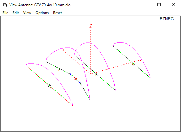
The bent DE (K6STI style) transforms from approx. 17 ohms to 50 ohms at feed point.
Date of issuing this design: 26th of Feb. 2022.
Current Distribution & 3D pattern

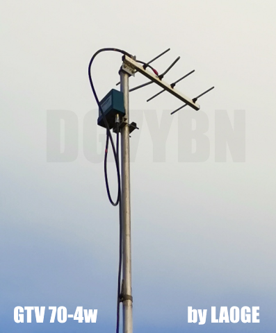
GTV 70-4w built by Bent, LA0GE
This website has been viewed by how many 70 cm enthusiasts since Feb. 2022?
Performance Data
                     Elem. 10 mm
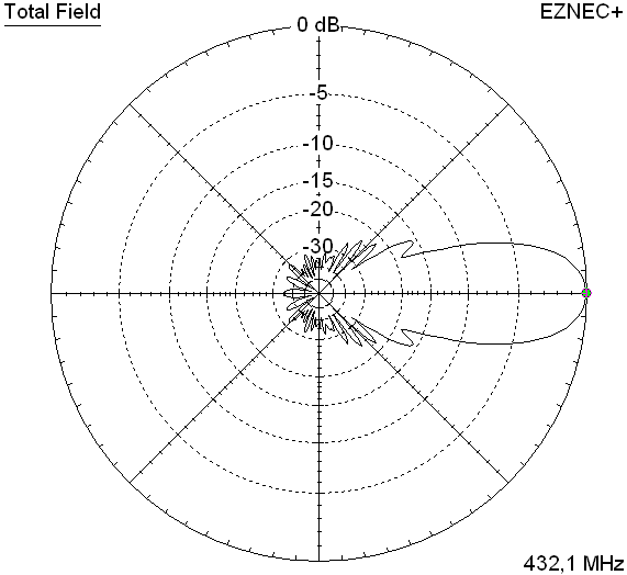
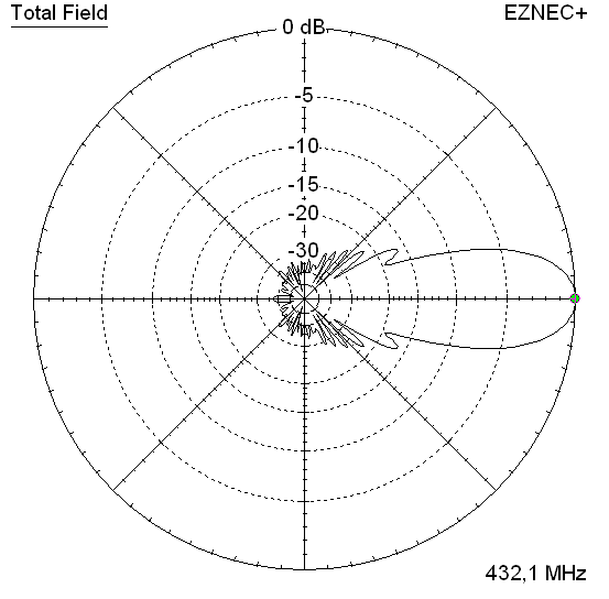
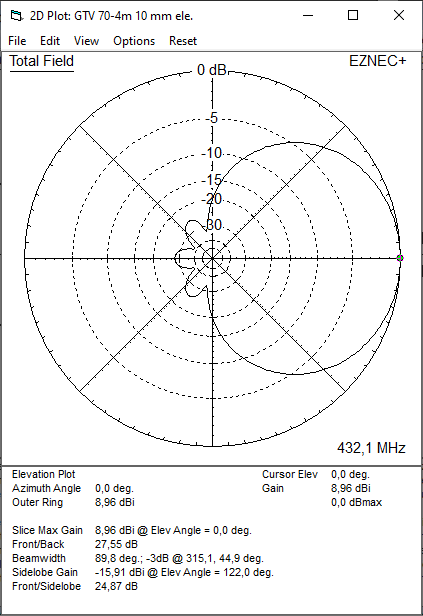
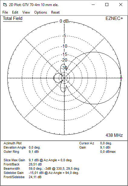
Gain vs. isotr. Rad.   9.0 dBi
Gain vs. Dipole        6.8 dBD
-3 dB E-plane         60.0 deg.
-3 dB H-plane         89.8 deg.
F/B                  -27.6 dB
F/R                  -23.9 dB
Impedance               50 ohms
Mechan. Length         332 mm plus boom offsets
Electr. Length        0.48 λ

Stacking Dist. h-pol. per DL6WU ... mind DL6WU formula is for approx. > 10 ele.
top-to-bottom         0.49 m or 1.6 ft ... suggestion YBN: 440 mm
side-by-side          0.69 m or 2.3 ft
Geometry

Ø8 mm Elements - On Boom - Dimensions (BC acc. DG7YBN)

|
Ele. 8.0 mm DE 10 mm Boom 15 x 15 mm |
"Ready to saw and drill" data for mounting elements on boom with BC according DG7YBN for standard insulators as sold by WiMo, Tino's Funkshop, HF Kits.nl, 7arrays:
Includes an SBC of 1.37 mm ... (434,0 - 432,5) MHz.

Other element diameters and boom sizes on request ...
Ø8 mm Elements - On Boom - Dimensions (BC acc. DG7YBN)

|
Ele. 8.0 mm DE 10 mm Boom 20 x 20 mm |
"Ready to saw and drill" data for mounting elements on boom with BC according DG7YBN for standard insulators as sold by WiMo, Tino's Funkshop, HF Kits.nl, 7arrays:
Includes an SBC of 1.37 mm ... (434,0 - 432,5) MHz.

Other element diameters and boom sizes on request ...
Ø10 mm Elements - On Boom - Dimensions (BC acc. DG7YBN)

|
Ele. 10.0 mm DE 10 mm Boom 20 x 20 mm |
"Ready to saw and drill" data for mounting elements on boom with BC according DG7YBN for standard insulators as sold by WiMo, Tino's Funkshop, HF Kits.nl, 7arrays:
Includes an SBC of 1.37 mm ... (434,0 - 432,5) MHz.

Other element diameters and boom sizes on request ...
Sketch of Bent Dipole

Pattern and VSWR Plots
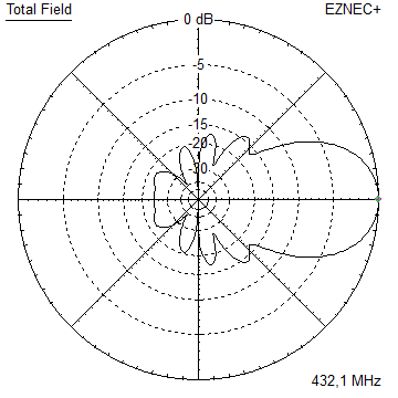
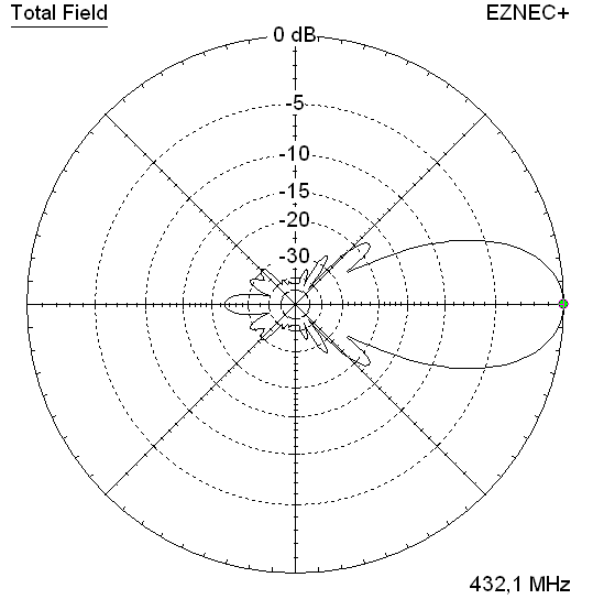
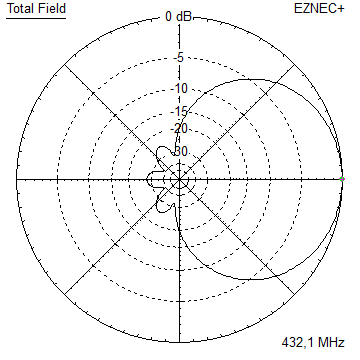
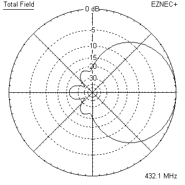
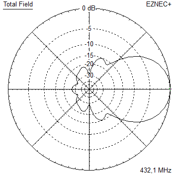
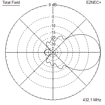
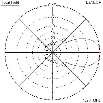
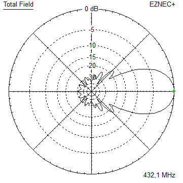
Elevation and Azimuth plot at 432.1 MHz

RL and SWR plot: S11 = Return Loss: -35 dB across 430-440 MHz

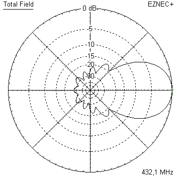
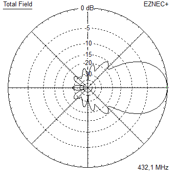
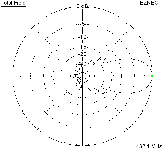
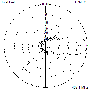
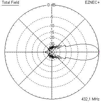
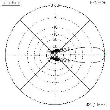
Elevation and Azimuth plot at 438.0 MHz

Downloads
None so far.
Stacking
• For Yagis of a length less approximately 2 wL the DL6WU formula does not deliver best performance.
Hence the stacking distances for the GTV 70-4w are 'handmade', optimised using NEC. For the GTV70-4w Yagis I suggest a vertical stacking distance of 440 mm.
• For very small Yagis the optimum stacking distances are that low, that mutual coupling between
the individual Yagis becomes a serious effect. Which spoils the VSWR. So that either an adaption of the Yagis
must take place or we just live with less Return Loss if practicable.
Elevation plot and data of 2 x vertical stack of GTV70-4w Yagis
Yaigs not modified. VSWR < 1.15 for 430 - 440 MHz, at 490 mm

Yaigs not modified. VSWR < 1.15 for 430 - 440 MHz, at 440 mm

Stacking Dist.
H-plane               0.-- m
E-plane               0.490 m / 440 mm
Elevation plot and data of 4 x vertical stack of GTV 70-4w Yagis at 440 mm each
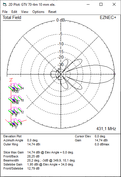
Stacking Dist.
H-plane               0.-- m
E-plane               0.440 m
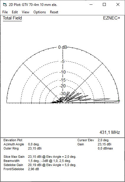
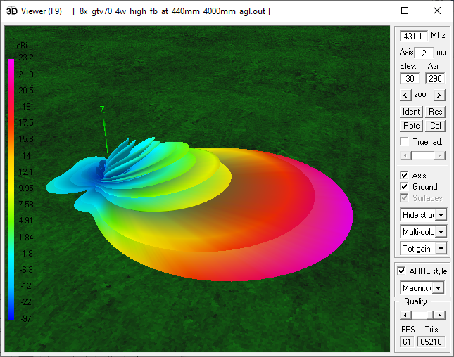
Elevation plot and data of 8 x vertical stack of GTV 70-4w Yagis at 440 mm each

Stacked over perfect ground,lowest Yagi at 4.0m agl.
Symmetrising 50 to 50 ohms Feedline to 432 MHz Bent DE
The principle is similar to the 1/4 Lambda coax. Adding 2 x 1/4 Lambda or a half wave line does not change anything but allows
to form a gentle bow below the boom or until behind the Reflector. Follow practical construction hints on "Building a Yagi" page.

 Attenzione!
Take care when lengthening the coax, measure the right length instead of refering to given v-factors only.
Attenzione!
Take care when lengthening the coax, measure the right length instead of refering to given v-factors only.A good choice may be the diam. 5 mm PTFE coax RG-142 B/U: real resonate length (432.2 Mhz as 3/4 Lambda) shield-shield is around 348 mm
 Find more information on Phasing & Matching Lines page
 73, Hartmut, DG7YBN

