-
• Main Page
- • Home
• Antennas - • 144 MHz
- Bent dipole GTV
144 MHz YagisGTV 2-7w: 2.7 m wide band width version of the low impedance, yet 50 ohms direct feed Low Noise Yagi with bent DE introduced in Dubus 1/2013
Elevation Plot

- YBN 3+7 SATA Satellite Yagi with 3 ele. for 145 MHz + 7 ele. for 435 MHz for handheld use
Elevation Plots
- YBN 2-2wA 50 ohms direct feed 2 ele. Yagi with high potential as broad beam Contest Stack.
See yourself and compare to DJ9HO Double Quads and 7ZB Oblongs. Full details on 2 and 4 Yagi stacks are given
3D Pattern of 4 x Stack

- YBN 2-5m (5-8)1.6 m high F/R, good willing 50 ohms direct feed Yagi as introduced with bent DE short version of the 5-8 in Dubus 4/2012
Elevation Plot

- YBN 2-6m 1.9 m long, good willing 50 ohms direct feed Yagi, related to the 5-8 project (same positions refl, dipole, D1, D2 ... same size folded dipole)
Elevation Plot
- YBN 2-7m 2.8 m high F/R, good willing 50 ohms direct feed Yagi, related to the 5-8 project (same positions refl, dipole, D1, D2 ... same size folded dipole)
Elevation Plot
- YBN 2-7mz 28 Ω2.8 m high F/R, good willing 28 ohms direct feed Yagi
Elevation Plot

- YBN 2-8m (5-8)3.6 m nice G/T, good willing 50 ohms direct feed Yagi as introduced with bent DE expanded version of the 5-8 in Dubus 4/2012
Actually it seems to be so good that DK7ZB decided to use it as draft for the 8 ele. OWM he just published.
Elevation Plot
- YBN 2-8mz 28 Ω3.6 m 25/28 ohms version of the YBN 2-8m
The stacked 25 ohms Yagi can easily be phased with 50 ohms coax cables
Elevation Plot
- YBN 2-9mz 28 Ω4.3 m high F/R, high G/Ta 28 ohms Yagi
Elevation Plot

- YBN 2-9m4.5 m moderate band width, low Antenna Temperature, good willing 50 ohms direct feed Yagi - a straigh DE version twin to the GTV 2-9m
Elevation Plot
- YBN 2-10w (5-8)5 m wide band, good willing 50 ohms direct feed Yagi as introduced with straight DE expanded version of the 5-8 in Dubus 4/2012
Elevation Plot
- YBN 2-10wz 12.5Ω5.1 m - 144.0 to 144.8 MHz wide band 12 ohms OWL-style Low Noise Yagi with straight DE and very low back lobes only
Elevation Plot
- YBN 2-12wz 12.5Ω6.8 m wide band 12 ohms OWL-style Low Noise Yagi with straight DE and very low back lobes only
Azimuth Plot:

- Bent dipole GTV
YBN 2-12wz wideband 12.5 ohms Yagi with straight dipole
144.0 to 145.6 MHz Wideband Antenna Version (OWA style)
This Yagi has very low back lobes for its length. It may serve as a single powerful antenna for Tropo and EME
or make a quiet contest antenna due to its high F/B. The straight DE may be matched to 50 ohms at feed point with an
improved DK7ZB style 2 x 50 ohms quarter wave line (see end of page).
Parameters are quite similar to the performance the GTV2-12mk2 offers. This Yagi thus may demonstrate that the bent DE
but transformates from low impedance to 50 ohms as an integrated member of the antennas structure.
Current distribution

Performance Data
Gain vs. isotr. Rad.  15.5 dBi
Gain vs. Dipole       13.4 dBD
-3 dB E-plane         31.8 deg.
-3 dB H-plane         34.2 deg.
F/B                  -30.7 dB
F/R                  -28.1 dB
Impedance             12.5 ohms
Mechan. Length        6770 mm
Electr. Length        3.25 λ

Stacking Dist. h-pol.    DL6WU     max. G/T
top-to-bottom           3.54 m      x.xx m
side-by-side            3.80 m      x.xx m
Geometry

        Pos.    Full Length    Full Length     incl. BC
                Free Space     Free Space   on 25x25 Boom

Refl.     0      1031.0         1026.0         1035.9
DE      208       976.0          976.0          985.9
D1      402       979.0          966.0          975.9
D2      694       958.0          942.0          951.9
D3     1236       945.0          928.0          937.9
D4     1886       929.0          910.0          919.9
D5     2628       919.0          898.0          907.9
D6     3414       908.0          884.0          893.9
D7     4276       899.0          877.0          886.9
D8     5140       891.0          866.0          875.9
D9     5997       887.0          862.0          871.9
D10    6770       869.0          842.0          851.9

                ele. 4 mm      ele. 8 mm      ele. 8 mm

4 mm elements insulated through boom BC:
Use DJ9BV BC numbers and nylon rivets on square boom as shown on BC-page
PLUS added Segmentation BC of +2.3 mm as below

On Boom BC:
SegmentationBC = +2.3 mm = (144.6 MHz - 144.2 MHz) * 5.85 mm/MHz
BaseBC (25x25) = +7.6 mm for semi-insulated on boom
Total          = +9.9 mm
Note: element lengths for Ø 8 mm fit 5/16" too

The Drivers diameter is 10 mm for all examples.
Use EZNEC's Auto-Segmentation at 380 MHz.
Pattern and VSWR Plots
Elevation and Azimuth plot at 144.1 MHz
SWR and Return Loss plots - simulated with 4nec2
Downloads
EZNEC file of this Yagi
EZNEC file of this Yagi as 4 bay using DL6WU distances
Stacking

Stacking Dist.    DL6WU Formula    max. G/T
H-plane               4.21 m        4.45 m
E-plane               4.39 m        4.60 m
Elevation and azimuth plot and data of 4 Yagi bay using DL6WU stacking distances


Gain vs. isotr. Rad.  21.47 dBi
Gain vs. Dipole       19.32 dBD
-3 dB H-plane         14.4 deg.
-3 dB E-plane         15.4 deg.
F/B                  -32.6 dB
F/R                  -32.6 dB
T_ant                223.6 K*
G/T                  -2.02 dB*
Theoretical numbers, no phasing line losses
nor imperfections caused by H-frame included
*) T_sky = 200 K, T_earth = 1000 K as in VE7BQH G/T table
Matching 12.5 to 50 ohms
Coax line transformer principle and applied concept = the ferrite improved DK7ZB - Match

 Attenzione!
Take care when lengthening the cables, measure the right length instead of refering to given v-factors only.
Attenzione!
Take care when lengthening the cables, measure the right length instead of refering to given v-factors only.A good choice may be the diam. 5 mm PTFE coax RG-142 B/U: real resonate length (144.1 Mhz) shield-shield is around 345 mm.
• 12.5 ohms to 50 ohms dipole box by IZ1AZA:
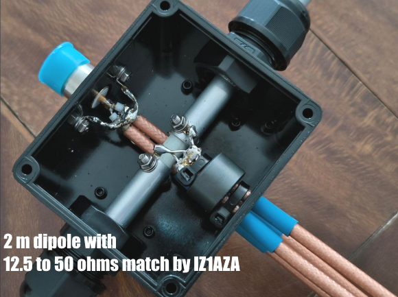

Photos: Kindly provided by IZ1AZA. Tnx Alex!
 Find more information on Phasing & Matching Lines page
 73, Hartmut, DG7YBN