-
• Main Page
- • Home
• Antennas - • 144 MHz
- Straight Dipole
144 MHz YagisYBN 2-9m: 4.5 m moderate band width, low Antenna Temperature, good willing 50 ohms direct feed Yagi - a straight DE version twin to the GTV 2-9m
Elevation Plot
- GTV 2-2mA 50 ohms direct feed 2 ele. Yagi with bent DE and potential as broad beam Contest Stack.
It can be used as back-to-back stack:
- GTV 2-4w1.0 m 144-146 MHz wide band width version of the Low Noise Yagi with bent DE as useful for satellite operation as for contesting thanks to high F/B and small volume of rear quadrants lobs in general.
Elevation Plot at 144.1 MHz

- GTV 2-5m1.6 m moderate to wide band width version of the Low Noise Yagi with bent DE as useful for satellite operation as for contesting thanks to high F/B and small volume of rear quadrants lobs in general.
Elevation Plot

- GTV 2-6m2.4 m moderate band width version of the low impedance, yet 50 ohms direct feed Low Noise Yagi with bent DE introduced in Dubus 1/2013
Elevation Plot
- GTV 2-7w2.7 m wide band width version of the low impedance, yet 50 ohms direct feed Low Noise Yagi with bent DE introduced in Dubus 1/2013
Elevation Plot
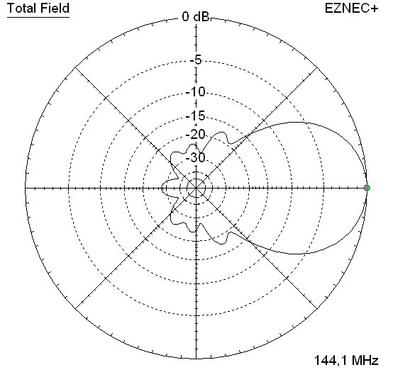
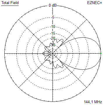
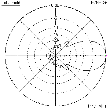
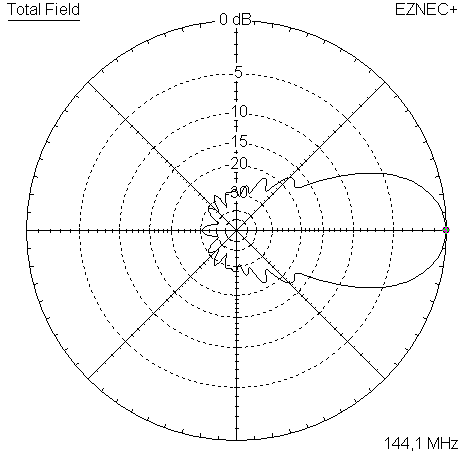
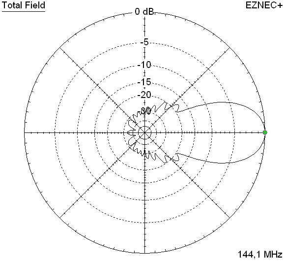
- GTV 2-7n3.1 m narrow band, max. G/T version of the low impedance, yet 50 ohms direct feed Low Noise Yagi with bent DE introduced in Dubus 1/2013
Elevation Plot
- GTV 2-8w3.7 m wide-band, still good G/T and nice F/B version of the low impedance, yet 50 ohms direct feed Low Noise Yagi with bent DE introduced in Dubus 1/2013
Elevation Plot
- GTV 2-8n3.8 m narrow band, max. G/T version of the low impedance, yet 50 ohms direct feed Low Noise Yagi with bent DE introduced in Dubus 1/2013
Elevation Plot

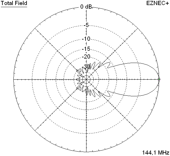
- GTV 2-9n4.3 m narrow band, balanced between low Antenna Temp. and G/T version of the low impedance, yet 50 ohms direct feed Low Noise Yagi with bent DE introduced in Dubus 1/2013
Elevation Plot

- GTV 2-9m4.5 m moderate band width, low Antenna Temp. version of the low impedance, yet 50 ohms direct feed Low Noise Yagi with bent DE introduced in Dubus 1/2013
Elevation Plot
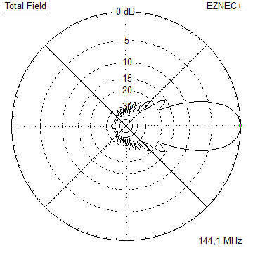
- GTV 2-10LT5.1 m moderate band width, lowest Antenna Temp. version of the low impedance, yet 50 ohms direct feed Low Noise Yagi with bent DE introduced in Dubus 1/2013
Elevation Plot
- GTV 2-11LT6.0 m moderate band width, lowest Antenna Temp. version of the low impedance, yet 50 ohms direct feed Low Noise Yagi with bent DE introduced in Dubus 1/2013
Elevation Plot
- GTV 2-12m mk2Improved 6.8 m version of the low impedance, yet 50 ohms direct feed Low Noise Yagi with bent DE introduced in Dubus 1/2013
Elevation Plot:
- GTV 2-12n6.8 m narrow band version of the low impedance, yet 50 ohms direct feed Low Noise Yagi with bent DE introduced in Dubus 1/2013
Elevation Plot:
- GTV 2-13m7.5 m version of the low impedance, yet 50 ohms direct feed Low Noise Yagi with bent DE introduced in Dubus 1/2013
Elevation Plot:
- GTV 2-14w8.4 m version of the low impedance, yet 50 ohms direct feed Low Noise Yagi with bent DE introduced in Dubus 1/2013
Elevation Plot
- GTV 2-16w10 m version of the low impedance, yet 50 ohms direct feed Low Noise Yagi with bent DE introduced in Dubus 1/2013
Elevation Plot
- GTV 2-18w11.7 m version of the low impedance, yet 50 ohms direct feed Low Noise Yagi with bent DE introduced in Dubus 1/2013
Elevation Plot
- GTV 2-19m12.4 m version of the low impedance, yet 50 ohms direct feed Low Noise Yagi with bent DE introduced in Dubus 1/2013
Elevation Plot

- Straight Dipole


GTV 2-7n Yagi mit gebogenem gespeisten Element
EME + SSB Schmalband - Version ... rein auf G/T gezüchtet
Diese kleine Yagi besitzt ein hohes F/B für ihre Länge. Sie kann als Kontestgruppe oder kleine, aber
effektive EME 4er-Gruppe dienen. Der gebogene Dipol (nach K6STI) transformiert von etwa 17 Ohm auf
50 Ohm am Speisepunkt für direkte Speisung.
Der Entwurf der GTV 7 Element Yagi geht auf den Wunsch zurück, eine schmalbandige und kurze
Yagi mit gebogenem Dipol zu haben, an der das Verhalten des gebogenen DE und Boom Korrekturen
getestet werden können. Und dies Dank der Schmalbandigkeit mit deutlichen Reaktionen des realen
Aufbaus. Daher bietet sich diese Yagi als Einstieg in den Bau von Yagi mit gebogenem DE bzw. Testen
von BCs mit unbekannten Haltern oder Bauweisen an.
Mit der schmalen Bandbreite und konzipierten niedrigen Rückzipfeln kommt hohe Leistung im Sinne
von Gewinn und niedriger Antennentemperatur - was sehr gutes G/T für eine Länge < 1,5 wl ergibt.
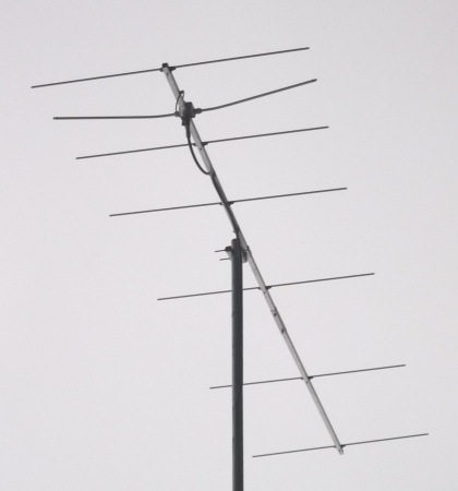
DK0BC mit 4 x vertikal GTV 2-7n:
Link zum


Leistungsdaten
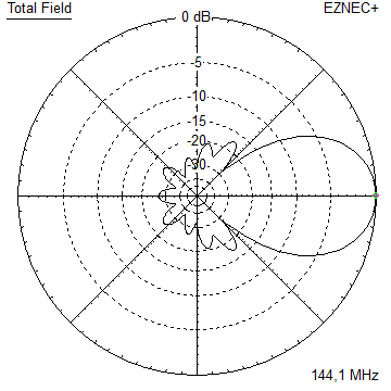
Gewinn isotr.         12.8 dBi
Gewinn gegen Dipol    10.7 dBD
-3 dB H-Ebene         42.4 deg.
-3 dB E-Ebene         49.8 deg.
F/B                  -27.4 dB
F/R                  -23.2 dB
Impedanz               50 ohms
Mechan. Länge        2994 mm
Elektr. Länge        1.44 λ

Stockungsabst. h-pol. (DL6WU) h-pol.
Oben/Unten            2.47 m
Seite/Seite           2.88 m
Geometrie
NEC Geometrie für 8 mm Elemente

Der Segmentatierungs BC beträgt 2.3 mm:
Er ist aus der Simulation der f_res von 144.20 MHz bei Auto Segmentierung bei 350 MHz und 144.60 MHz bei
Auto Segmentierung bei 144.1 MHz und Multiplikation des resultierenden Unterschieds mit * 5.85 mm/MHz gewonnen.
        Pos.    1/2 Länge  1/2 Länge
                  in NEC      in NEC

Refl.     0       505.0       502.0
DE(b)   194      100-471     100-471
DE(a)   275       0-100       0-100
D1      463       480.5       478.0
D2      867       471.0       468.0
D3     1510       460.0       457.5
D4     2302       446.0       443.0
D5     2994       428.0       425.5
                Ele. 1/4"   Ele. 8 mm

Notiz: Elementlängen für Ø 8 mm passen auch für 5/16"

Der Durchmesser des Dipols ist 10 mm für ale Ausführungen.
Es gilt EZNEC's Auto-Segmentation bei 350 MHz
Maße "fertig zum Sägen und Bohren" für Montage der Elemente auf 20 x 20 mm Boom mit Standardhaltern inklusive 30 mm Offset an den Enden:

Bitte beachten: Die Enden des gebogenen Dipols des Testaufbaus mußten um 38 mm gegen
die Lage im NEC Modell nach vorne verlegt werden für bestes SWR wie im VNA plot zu sehen.

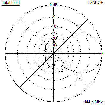
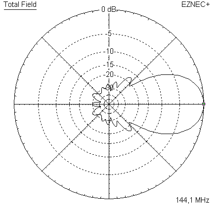
Strahlungsdiagramme und VSWR Plots
Strombelegung


Winkeldiagramme dieser Yagi für die BEMFV bei DM2BLE
RL und SWR Plot - simuliert

RL und SWR Plot - gemessen

gemessenes RL und SWR
 MHz        RL        SWR
144.2    -39 dB      1.0:1
Downloads
EZNEC Datei dieser Yagi
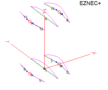
Stockung

Stockungsabst.    n. DL6WU Formel
H-Ebene               2.47 m
E-Ebene               2.88 m
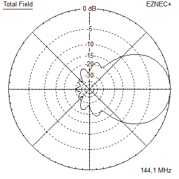
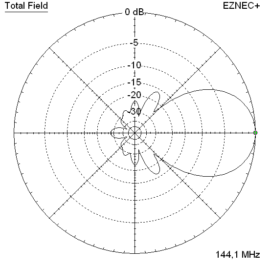
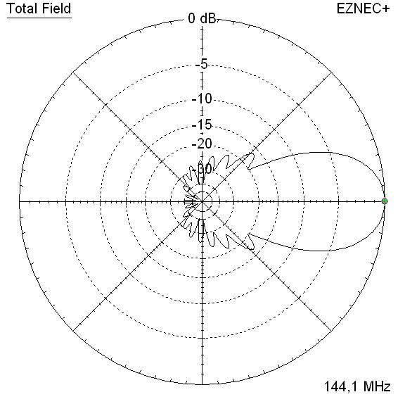
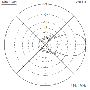
Elevations und Azimuth-Plot und Daten einer 4er-Gruppe mit Stockungsabständen nach DL6WU


Gewinn isotr.         18.7 dBi
Gewinn gegen Dipol    16.6 dBD
-3 dB H-Ebene         19.0 deg.
-3 dB E-Ebene         22.2 deg.
F/B                  -30.1 dB
F/R                  -24.2 dB
T_ant                242.7 K*
G/T                  -5.15 dB*
Theoretische Werte, weder Verluste in Stockungsleitungen
noch Imperfektionen durch den Rahmen sind eingeschlossen
*) T_sky = 200 K, T_earth = 1000 K wie in der VE7BQH G/T Tabelle
73, Hartmut, DG7YBN