-
• Main Page
- • Home
• Antennas - • 144 MHz
- Straight Dipole
144 MHz YagisYBN 2-9m: 4.5 m moderate band width, low Antenna Temperature, good willing 50 ohms direct feed Yagi - a straight DE version twin to the GTV 2-9m
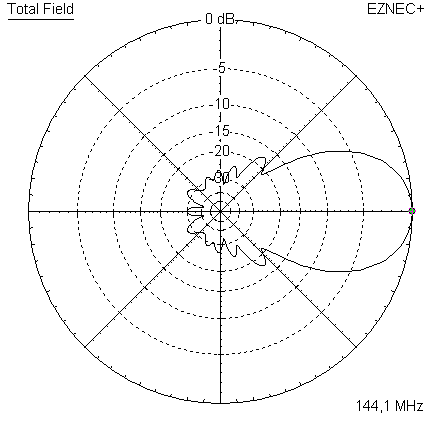
Elevation Plot
- GTV 2-2mA 50 ohms direct feed 2 ele. Yagi with bent DE and potential as broad beam Contest Stack.
It can be used as back-to-back stack:
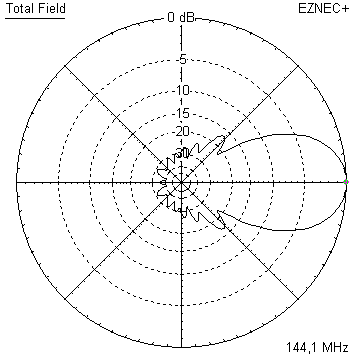
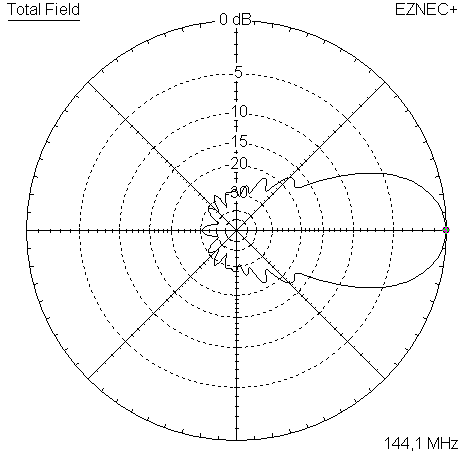
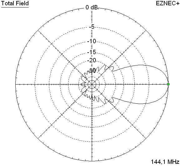
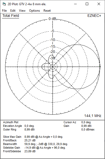
- GTV 2-4w1.0 m 144-146 MHz wide band width version of the Low Noise Yagi with bent DE as useful for satellite operation as for contesting thanks to high F/B and small volume of rear quadrants lobs in general.
Elevation Plot at 144.1 MHz

- GTV 2-5m1.6 m moderate to wide band width version of the Low Noise Yagi with bent DE as useful for satellite operation as for contesting thanks to high F/B and small volume of rear quadrants lobs in general.
Elevation Plot

- GTV 2-6m2.4 m moderate band width version of the low impedance, yet 50 ohms direct feed Low Noise Yagi with bent DE introduced in Dubus 1/2013
Elevation Plot
- GTV 2-7w2.7 m wide band width version of the low impedance, yet 50 ohms direct feed Low Noise Yagi with bent DE introduced in Dubus 1/2013
Elevation Plot
- GTV 2-7n3.1 m narrow band, max. G/T version of the low impedance, yet 50 ohms direct feed Low Noise Yagi with bent DE introduced in Dubus 1/2013
Elevation Plot
- GTV 2-8w3.7 m wide-band, still good G/T and nice F/B version of the low impedance, yet 50 ohms direct feed Low Noise Yagi with bent DE introduced in Dubus 1/2013
Elevation Plot
- GTV 2-8n3.8 m narrow band, max. G/T version of the low impedance, yet 50 ohms direct feed Low Noise Yagi with bent DE introduced in Dubus 1/2013
Elevation Plot

- GTV 2-9n4.3 m narrow band, balanced between low Antenna Temp. and G/T version of the low impedance, yet 50 ohms direct feed Low Noise Yagi with bent DE introduced in Dubus 1/2013
Elevation Plot

- GTV 2-9m4.5 m moderate band width, low Antenna Temp. version of the low impedance, yet 50 ohms direct feed Low Noise Yagi with bent DE introduced in Dubus 1/2013
Elevation Plot
- GTV 2-10LT5.1 m moderate band width, lowest Antenna Temp. version of the low impedance, yet 50 ohms direct feed Low Noise Yagi with bent DE introduced in Dubus 1/2013
Elevation Plot
- GTV 2-11LT6.0 m moderate band width, lowest Antenna Temp. version of the low impedance, yet 50 ohms direct feed Low Noise Yagi with bent DE introduced in Dubus 1/2013
Elevation Plot
- GTV 2-12m mk2Improved 6.8 m version of the low impedance, yet 50 ohms direct feed Low Noise Yagi with bent DE introduced in Dubus 1/2013
Elevation Plot:
- GTV 2-12n6.8 m narrow band version of the low impedance, yet 50 ohms direct feed Low Noise Yagi with bent DE introduced in Dubus 1/2013
Elevation Plot:
- GTV 2-13m7.5 m version of the low impedance, yet 50 ohms direct feed Low Noise Yagi with bent DE introduced in Dubus 1/2013
Elevation Plot:
- GTV 2-14w8.4 m version of the low impedance, yet 50 ohms direct feed Low Noise Yagi with bent DE introduced in Dubus 1/2013
Elevation Plot
- GTV 2-16w10 m version of the low impedance, yet 50 ohms direct feed Low Noise Yagi with bent DE introduced in Dubus 1/2013
Elevation Plot
- GTV 2-18w11.7 m version of the low impedance, yet 50 ohms direct feed Low Noise Yagi with bent DE introduced in Dubus 1/2013
Elevation Plot
- GTV 2-19m12.4 m version of the low impedance, yet 50 ohms direct feed Low Noise Yagi with bent DE introduced in Dubus 1/2013
Elevation Plot

- Straight Dipole
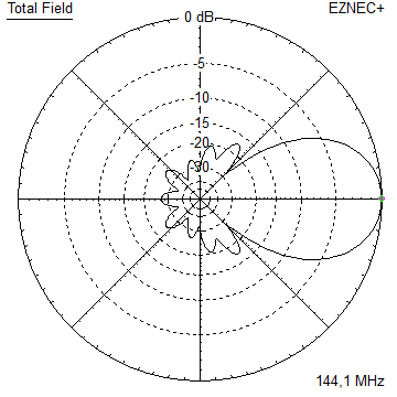
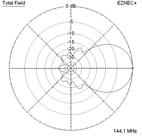
GTV 2-4w Yagi with bent Driven Element
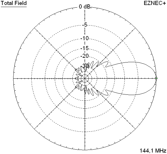
For the given bandwidth this Yagi shows respectable low Antenna Temperature and a moderate gain for its length. I would not recommend this design for a contest stack in the first place because the azimuth plot is not as clean to the rear. This seems to be a challenge with whatever 5 element Yagi as soon as we put some bandwidth in. However this design is planned to serve as a xpol Yagi for satellite communication which can be built with less trouble. When cricular polarised the pattern looks fine for a wider 5 element.
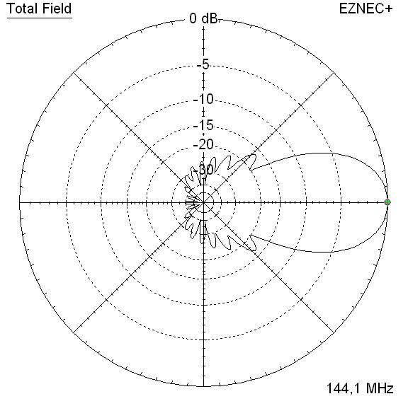
There is a satellite band version, which when built as Cross Yagi, when circular poarised shows a respectable clear rear of the pattern for sch a boom length. With this xpol version the distance between v- and h-plane is a full 1/4 wavelength. So that feeding is uncomplicated via 2 same length 50 ohms coax cables and a power splitter for instance.
The bent DE (K6STI style) transforms to 50 ohms at feed point for direct feed. Design date of issue: 2025.01.24
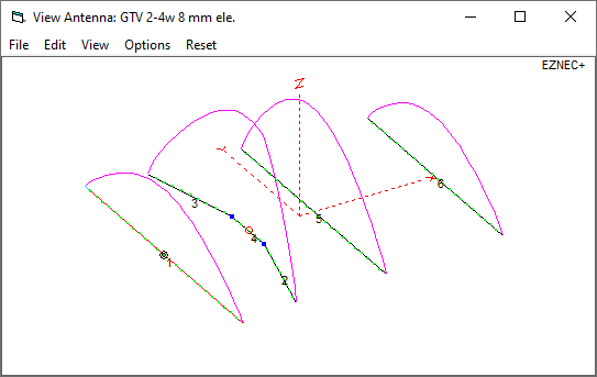
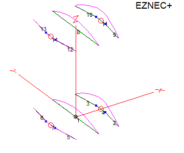
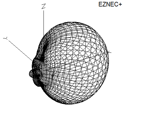
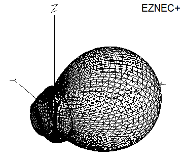
GTV 2-4w 3D pattern plot at 144.1 MHz
Performance Data
Specs: with 8 mm elements @ 144.1 MHz
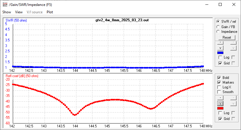
Gain vs. isotr. Rad.   8.99 dBi
Gain vs. Dipole        6.8 dBD
-3 dB E-plane         59.9 deg.
-3 dB H-plane         89.2 deg.
F/B                  -25.2 dB
F/R                  -20.3 dB
Impedance               50 ohms
VSWR Band Width       1.02:1*
Mechan. Length         995 mm plus offsets
Electr. Length        0.48 λ

Stacking Dist. h-pol. (144.3 MHz)
top-to-bottom         1.481 m or 4.8 ft
side-by-side          2.084 m or 6.8 ft

*) as in VE7BQH G/T table = at 145.00 MHz
How many VHF operators have been looking up this design since Febr. 2025?
Geometry
This Yagi with 8 mm elements on a 20 x 20 mm boom with standard insulators

|
Ele. 8.0 mm DE 10 mm Boom 20 x 20 mm |
|

"Ready to saw and drill" data for mounting elements on boom with BC according DG7YBN for standard insulators as sold by WiMo, Tino's Funkshop, HF-Kits NL, 7arrays:
Includes an SBC of 2.05 mm
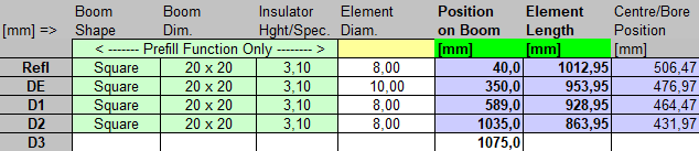
Foremast mount version, 400 mm rear offset (remember, with elements mounted on boom you may alter the rear offset)
The Drivers diameter is 10 mm.
The EZNEC model is done with Auto-Segmentation at 380 MHz

Ø 3/16 inch Elements, 3/8 inch Dipole - Through Boom - Dimensions (BC acc. SM5BSZ's BC.exe)
Imperial Boom 1"
|
This table is only valid for: Boom shape: square Boom dim: 1 x 1 inch Wall thickn.: 1.6 mm Holes in boom: 7.7 mm Offset rear: 40 mm Offset front: 40 mm |
Note: All the above include a "Segmentation Density Correction" (SBC) of 2.93 mm per element.
Note: with through Boom BC it is important to stick to the boom end offsets given below!
Read abt. the SBC here
![]()
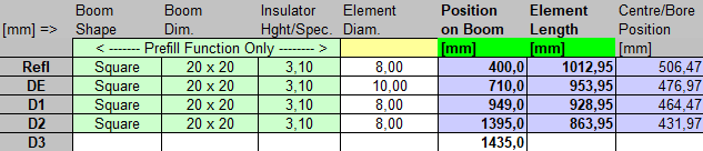
Imperial Boom 1"
|
This table is only valid for: Boom shape: square Boom dim: 1 x 1 inch Wall thickn.: 1.6 mm Holes in boom: 7.7 mm Offset rear: 500 mm for foremast mounting Offset front: 40 mm |
Note: All the above include a "Segmentation Density Correction" (SBC) of 2.93 mm per element.
Note: with through Boom BC it is important to stick to the boom end offsets given below!
Read abt. the SBC here
![]()
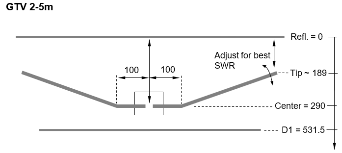
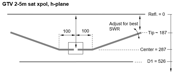
Sketch of Bent Dipole
Pattern and VSWR Plots
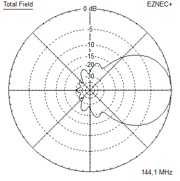
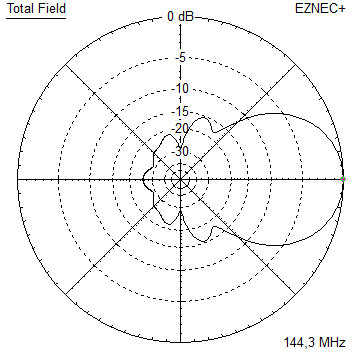
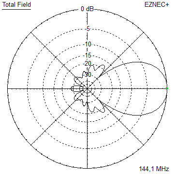
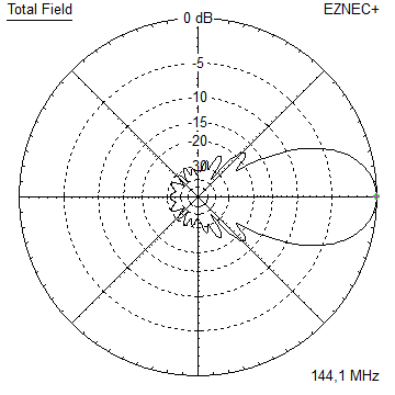
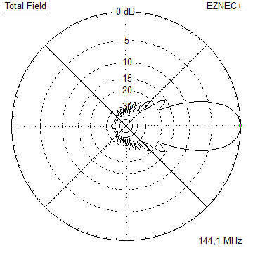
Elevation and Azimuth plot at 144.3 MHz, 4.76 mm element version:
RL and SWR plots - simulated
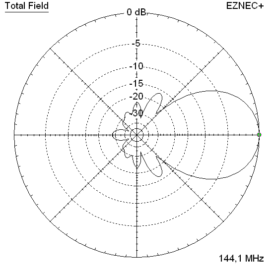
Satellite xpol. Version
With this xpol version the distance between v- and h-plane is a full 1/4 wavelength. So that feeding is uncomplicated via 2 same length 50 ohms coax cables and a power splitter for instance. When bulding this, mind that the down planes differ slightly, see buiding table and sketch of bent dipole for v- and h-plane.
Circular polarised 3D pattern

Circular polarised pattern with data, 145.8 MHz, elements 4.763 mm = 3/16 inch

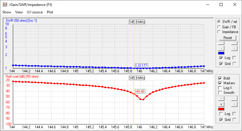
VSWR and Return Loss (S11) with a bit of overhead when wet
Ø 3/16 inch Elements, 3/8 inch Dipole - Through Boom - Dimensions (BC acc. SM5BSZ's BC.exe),
offset element planes 514 mm = 1/4 wl on 145.9 MHz (Mind this refers to the two exiters, the dipoles distance).
Imperial Boom 1"
|
This table is only valid for: Boom shape: square Boom dim: 1 x 1 inch Wall thickn.: 1.6 mm Holes in boom: 7.7 mm Offset rear: 500 mm Offset front: 40 mm |
Note: All the above include a "Segmentation Density Correction" (SBC) of 2.93 mm per element.
Note: with through Boom BC it is important to stick to the boom end offsets given below!
Read abt. the SBC here
![]()
Sketches of Bent Dipoles

Downloads
None so far.
Stacking
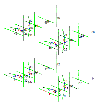
Stacking at 1.80 m e, h for circular polarisation
which is slight understacking against distances per DL6WU formula.
Plot and data of 4 stacked in H-configuration GTV 2-5m sat xpol
Antenna View & Elevation Pattern

73, Hartmut, DG7YBN