Fundamental knowledge about Average Gain
• Average Gain (AG) is factorised Radiation Efficiency
• If Radiation Efficiency is 98.7% then AG is 0.987
• Radiation Efficiency is related to sum of gain per radiaton patterns segments over Phi and Theta
• Phi (= φ) and Theta (= θ) are the radation patterns azimuth and elevation referencing angles
• Radiation Efficiency is percentage of power found in whole 3D radiation pattern against fed in power
• Ideal simulation outcome produces 100 percent of Radiation Efficiency when using lossless wires
• Thus aim of the "AG-Test" (AGT) is to find out if the lossless design busts 100% of Radiation Efficiency = AG > 1.000
• AG_lossless = AGT > 1.000 would mean that we radiate more than we feed; which can not be ...
• Which shows that the model, as computed by the NEC-kernel has a convergence issue
• Most simulations show slighty diverted outcome i.e. Power Gain > or < 100 percent
• Using KF2YN's AG correction allows to standardises actual simulation outcome to 100.0 percent = AG = 1.000
• Thus key figures like Antenna Gain and Temperature, which result in G/T can be lifted on a standardised AG-level
• This we appreciate when comparing antenna designs like in the VE7BQH G/T tables
The set of formulas put up by KF2YN:
The set of formulas shown by KF2YN in Dubus 4/2010 in the way I write them today:

• The last one for T_loss.corr was added by him later, was not part of the set shown in Dubus.
• num = numerical value
• lossless = means value from antenna model with wire losses put to zero
• lossy = menas value for antenna model with wire losses put to specific used material
• AVG = Average Gain as numerical value
What does a typical AG overshoot look like?
Neither NEC2 nor NEC4 will get the tapering that right that the AG fits to 1.000 absolutely. Not so for the untapered model. So this experiment offers a view on how much numbers go stray on a design with an 'imperfection' that can be switched on/off by just editing the Ø of the middle section of the DE.
The image shows same Yagis pattern with tapered and not tapered DE

Do not get confused reading the table below, AG(T) is specified for computed with lossless wires.
The shown numbers are for comparism only. Typical AGs for Yagi designs without convergence issue when using lossy wires are around 0.97x ... 0.98x. The delta to an AG(T) = 1.000 relects wire losses, we find these expressed as T_loss in Antenna Temperature computations like when using TANT.
T_loss is derived by the difference between Radiation Efficiency with and without wire losses applied. A negative T_loss means a gain. That can not be. This is yet another signal for the convergence overshooting the 100%.
                        tapered       not taperd
    AG (lossless)       1.051          1.000
    AG (Aluminum)       1.030          0.981
    Gain (lossless)     15.89 dBi      15.68 dBi
    Gain (Aluminum)     15.81 dBi      15.60 dBi

    Single Yagis Antenna Temperature and G/T - ratio
    T_loss               -8.8 K          5.6 K
    T_ant               230.3 K        233.2 K
    G/T                 -7.81 dB       -8.08 dB

    and with KF2YN's correction applied on the tapered version
    T_loss = 5.6 K    T_ant = 233.16     G/T = -8.09
What designs may hold a convergency issue?
• any tapering is highly likely to cause an AGT > 1.03
• any sharp bends are likely to cause an AGT > 1.01
Unless manipulated segment densities are used; such as using much lower segmentation density on the bends, which (a) is not recommended acc. NEC manual and (b) just works out since the convergence of whatever model is less at lower overall segmentation density (refering to less than approx. 12 segments per half wave).
How to check the Average Gain number
• EZNEC by Roy Levallen, W7EL
Edit 'Wire Loss' to 'zero', run 3 dimesional pattern. EZNEC shows the AG when doing a 3 D pattern in its main windows bottom line

• 4nec2 by Arie Voors
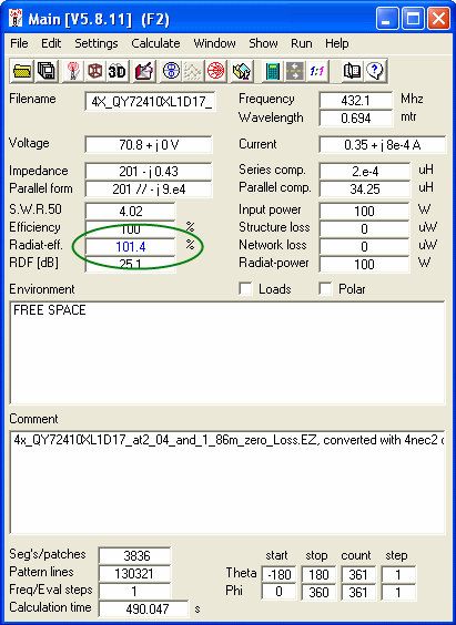
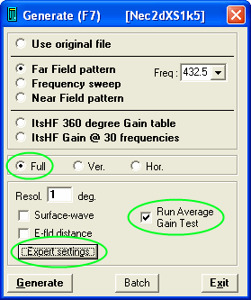
Edit NEC LD-card, set wire losses to zero and run 'Full Far Field Pattern'. Using older versions of 4nec2 we have to chose ‘calculate’ in the main menu, then ‘NEC output-data’ and chose ‘Far Field pattern’, opt for ‘Full’ pattern, click ‘expert settings’ and select option ‘1: average gain’. From version 5.8.11 on 4nec2 shows the Radiation Efficiency with one digit behind the decimal separator (tnx Arie!). This Radiation Efficiency is equal to Average Gain when divided by 100.

How to edit the LD card:
Set 4nec2 to use the "NEC editor (new)" as Geometry Editor
Menu -> Settings -> NEC editor (new) // Ctrl+F4;

use AGT function, which will set all wire losses to zero during the test run automatically


73, Hartmut, DG7YBN