Main Chassis Relays on Socket Relay Unit (PB-2354) inside the PA Cage: RL01 RF Unit (PB-2342) IF Unit (PB-2343) Local Unit (PB-2345) Final Board (PB-2355)
Relays en Detail & Other
Relay Data Meter Lamps Replacement Things I would do next time at it
Yaesu FT-102 Relay Replacement
Preface
About three years ago I bought myself a relatively cheap FT-102. The front plate looked like it had
been involved in a traffic exident but the price was alright. Collectors of this Yaesu benchmark: do not blame me for
the front plate mod and scratches - I bought it like this, honestly. And with a bit fiddly tuning it did
in excess of 160 W out from 160 m on. At that time the RX seemed alright. Though an occasional extra
click on the Mic PTT had to encourage the RX to come up bright. The other sign of worn relays which is
mentioned unisono: is a deaf RX when switching off the RX amplifier. With the RX only coming back to life
after another push on the PTT.
This seems to be the dawn of when the relay issues are becoming serious I think. And when I put my FT-102 back
as part of the station after 2 years of non use ... well that was it. RX deaf, hollow space like sound and
no signals on no band ...
Actually I had much respect opening the case of the FT-102 at all. But as I knew that with time the relay
issue would but grow and finally it had to be done ... . Follow me on my journey through the FT-102s relays.
Read all the mentioned other FT-102 relay replacement websites, I might have missed some things, and it is good
to have a second view on complexe topics and then take to the task or find someone who does it for you.
This FT-102's serial no. is: 2 H 010887
First no. = year of production, that should then be 1982 here? A very early model so.
Other websites about the FT-102
• NC4L's Yaesu FT-102 Resources
• EB5AGV's Yaesu FT-102 page
• PDF: FT-102 Survival Guide - Fox Tango International
How many FT-102 enthusiasts have visited this website since May 2016?
Transceiver of Champions?
... nowadays maybe 'Transceiver of Champions in handling the small soldering iron'
at least until the relay replacement rally is done. Which is why I liked to add this tutorial.
'One might be baffled by the excellent receiver dynamic range ...'
• Noise Floor (MDS): -127 dBm (with CW filter)
• IP3: +18 dB (80 m), +19.5 dB (20 m)
• Receiver Dynamic Range: 95 ... 102 dB
• No synthesiser or PLL noise, because there is none
• Capable bandpass filters, same technology as in the FT-1000MP Mark V field
• Lowest transmitter distortion ever measured by QST: -40 dB (14 MHz) at nominal input power
Read in full at NC4L
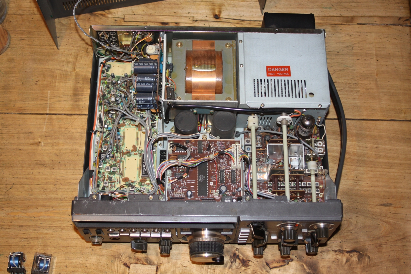
Top view on the opened FT-102
View this photo enlarged
On the right, below the PA cage, with all the tuning axis rods running above it, we find the RF Unit board which
has the majority of tricky to replace small relays embedded. See all the filter coils?
Bottom view on the opened FT-102
View this photo enlarged
Attenzione!
Before lifting any of the covers disconnect the FT-102 from mains and WAIT a couple of minutes to allow the PA power
supplies HV capacitors to discharge. Do not fool around with High Voltage. This PA runs 900 V DC. Which is lethal.
Be warned now!
Overview an relays to replace on what unit
Relays listed per unit
• Main chassis
Holds RL 1, RL2: 2 similar, relatively large standard socket plug in relays
• Relay Unit (PB-2354) inside PA cage
Holds a single RL01 (power contact relay that looks smaller then one might think, 10 A contacts)
• RF Unit (PB-2342) ... the board with the input RX amp, 1st mixer, filters
Holds RL01, RL03 (12 V miniature relays), RL02 (the tricky, obsolete in pins to contacts one that needs board or relay mod.),
RL04, RL05 (24 V miniature relays)
• IF Unit (PB-2343)
Holds RL01 (12 V miniature relay)
• Local Unit (PB-2345)
Holds RL01 (12 V miniature relay)
• Final Board (PB-2355) ... aka. Final Unit ... or PA board
Holds RL01 (12 V miniature relay)
Total Numbers of Miniature Relays
• 12 V miniature relay = all the same (5 pcs)
• 12 V miniature relay, the odd RL02 on the RF Unit (1 pcs)
• 24 V miniature relay = all the same (2 pcs)
Number of larger relays
• 12 V big socket style ones (2 pcs)
• 12 V power contact print relay (1 pcs)
Which sums up to 11 relays in total
Before Starting
Do you know whats ahead? Are you prepaired? Read this first please
... working on the RF Unit
It is not every day that I issue caution warnings. Not on my amateur radio website (hi).
Reading my antenna pages hopefully makes clear that I love to enable hams to build
great things. And to enable them by providing the knowledge associated with the tasks.
Now there are relays easy to replace in the FT-102. The Main Chassis RL 1 and RL 2. You do not
even need to swing the soldering iron for that. Replacing the Relay Units final TX / RX relay is a warm up
for the heavy tasks. And then there is what these words of caution are about: The RF Units challenges
to even get RL05 distracted from the board or find a proper replacement for the obsolete type of RL02
with NO replacement at all and the only way to do this is a tricky mod or leave it in.
To get them all replaced needs skills, nerves, gutts, time and caution or you mess up the TRX.
So please take some advice:
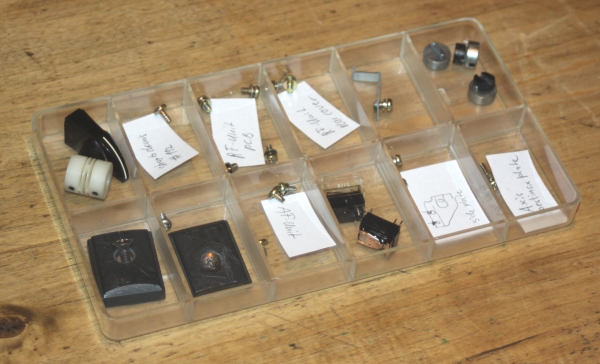
Use an assortment box and notes for screws per unit and small parts anyway
Make some notes about what wire belongs where for resoldering, before unsoldering it.
All over a sudden you have to stop working on something and the next day you probably do not recall all details ...
See my original, not cleared paper sheet I sketched during working on the RF Unit.
I gave the screw for the black-to-gnd stiff wire on the lower side a '#112 because its different to the others,
so it got its little paper note #112 own place in the box.
Good Luck then! The FT-102 being such a nice rig when running fine seems worth all this!
Main Chassis Relays RL 1 & RL 2
This is the easy bit. Really easy going, you not even need to come close to a soldering iron for changing this pair.
The RL 1 and RL 2 are straight standard socket type industrial relays around EUR 6.50
Read a step-by-step description how to replace the Main Chassis relays
Location of RL 1 & RL 2, note the standard sockets (relays taken out already)
The original RL 1 & RL 2 - one plastic cap missing
The original RL 1 & RL 2 (obsolete FUJITSU FRL263-DO12/04CS) with the replacement relays on left
One of the original relay with the repalcement relay on left (Finder 55.34.8.012.0040 - 12 V type)
contact material is AgNi, IP 40, socket type is 4CO (4PDT) contact configuration
Just plug them in ... and the first job is done and dusted
Make sure to get the wire straps on again or your new relays could unplug when the FT-102 is shipped or moved
about in any unsteady way.
Relay Unit (PB-2354) inside the PA Cage: RL01
This is your warm up coarse to get into gear for overhauling the RF Unit
Read a step-by-step description how how to replace the Relay Unit relay RL01
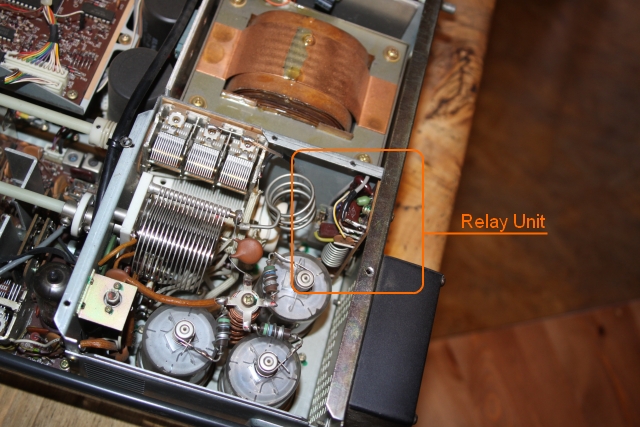
How to access the small Relay Unit PCB
Take off the PA cage cover plate, apart from the obvious screws on the top covers sheet
there is one on the rear side. The screwdriver is engaged on it here
.. ah, there the wee PBC hides ...
This screw fastens the small PCB's upside.
The PL-bushing is attached to the PCB and fastens it on the lower side.
Now the Relay Unit PCB is loose but we don't get it out as there are two
quite short wires soldered to it reaching thru the mid chassis base plate.
And also the space towards the tubes ad all is too small to get the PL-bushing
back in far enough ..
So what now? .. uhmm, I am afraid we have to loosen the rear chassis plate
Before we do that we need to see if all is clear to move it out backwards by an inch.
See this resistor connected to the chassis rear plate?
Its lead needs to be cut in order to move the chassis plate off far enough to get the PL-bushing out
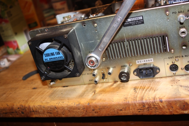
Now unscrew the chassis rear plate and bull back on PA cage side by approx. 2o mm carefully
to enable the PL-bushing slipping out to the inside of the PA cage. See photo: rear plate screws
in orange.
Now pull back the chassis rear plate steadily. (And what did I see ... surprise, surprise)
High time for a change ... see the burnt housing of this relay and black contacts
Replacement relay (on right) and original relay (Omron G(?)2 U - 113P 13309)
(Omron G2U-112P/10V acc. foxtango.org website)
Replacement relay (Finder 36.11.9.012.4011 - 12 V type, sealing RT III = wash tight, 10 A)
This close up shows where to find the pins of relay RL01 on the rear side
Resoldered with replacement relay
However, replacing the two Main Chassis relays RL 1 + RL 2 and this bruised Relay Units RL01 in a first haul
did not help an inch restoring the RX qualities. It was a necessary step though.
RF Unit (PB-2342)
Completed except for the odd RL02
Read a step-by-step description how to replace the RF Units relays
Fixing the RF Unit can theoretically be done in two ways.
Either do the operation while the board is still mounted inside the FT-102.
Or take in out, or at least lift the board while it is still wired.
So here is my experinece as far as I went. And sorry .. during that phase I wasn't cool enough
to keep on doing tracking photos
In order to work on the installed RF Unit its downside can be accessed by removing the AF Unit
and the backside RF Unit shield (2 screws). Retrospectively this enables changing the RL03 and RL04
by 'trained personal' (at least I managed that in about 15 minutes), Maybe also RL01.
But when it comes to the odd RL02 and the necessary modification of either board or relay around that ...
and last the RL05 I have my doubt if this can be done 'in style' with the RF Unit still in place.
So I replaced RL03 and RL04 while the board was still mounted, then tried oxide removal spray on the rest,
trying to back out from replacing the others ... hi.
This marks end of day one. I was at this for about 4 hours. With now replaced Main Chassis RL 1 + RL2,
Relay Units RL01, RF Units RL03, RL04 and sprayed RL01, RL02 (RL05 could not be accessed as cover does not
come off) plus IF Units RL01 the RX behaves almost ok. An occasional second push on the PTT does it now.
Where do we go from here?
I decided to take out the RF Unit board and finish this job in style. To find out why not even the top cover comes
off RL05 and access RL01 more easily and also to make a plan how to fix the odd RL02
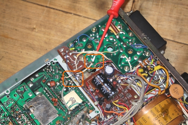
Unscrewing the RF unit board: Besides screws in all corners there is a 'hidden screw'
it took me quite some time to discover. The screwdriver is pointing right at it.
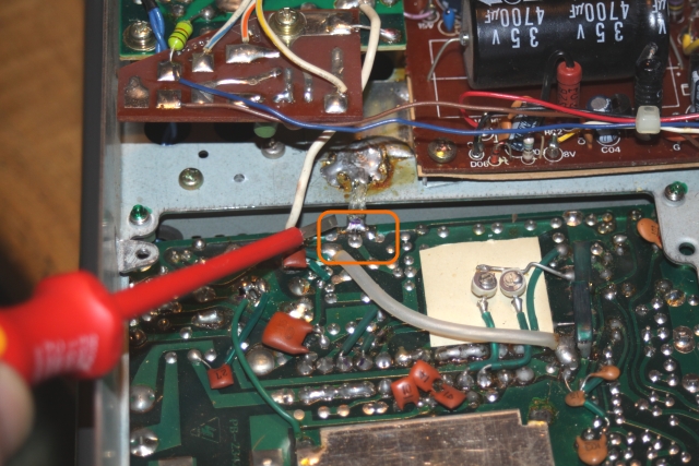
Besides the two wires on the upper side (br, wt) leading to the PA cage, there is a thicker white one on
the down side of the chassis leading to the Final Unit PCB. Unsolder this.
The screwdrivers tip is pointing right at the solder point (for you to know were to resolder it ... )
On the down side there is a very short to-gnd-strap from chassis to RF Unit PCB. Unsolder this as well.
The odd RL02:
here the evil sleeps ... hi, location of RL02 on the RF Unit
The odd RL02 from the PCB's downside, note also the pin locations of RL01, taken out already
The piece of board the odd RL02 is on. 'Digitally Remastered' version of EB5AGV's FT-102 Relay Substitution Tutorial
This marks end of day two. With now also replaced RF Units RL01, dismounted RL05 and making headroom towards
a decision how to deal with the odd RL02 challenge ... I had to realise I did not order a second 24 V type miniature
print relay as replacement for RL05, but 3 hours spent on a tricky task is enough for one day.
Day three, after a weeks break waiting for the missing relay
Fox Tango OR Criminal Tango?
getting under way after a halt waiting for a missing 24 V relay ...
A final look on the board and the substitute relay for the odd RL02 made me back out from the idea
of replacing that one. Full Stop. Call me a Sissi but this gamble isn't for me. The more since all the
cross wiring solutions for getting the pins of ablternative relays sorted are maybe not what we really
want RF wise.
Replaced RL05 for which the front Pertinax beam of the bandswitch ensamble has to be removed
because even if one gets the original RL05 out, the replacement relay is not going to fit in as it
is a few millimeters higher. But luckily the Pertinax brigde does not need to be modified.
Re-instaling the RF-Unit PCB
I was so glad to find my markings 'br' and 'wt' here after one week of not working on the FT-102!
Do not screw in the RF Unit board until the front panel bandswithc knob thru to PA cage axis clutches
are in place! There is NO space to fit them when you can not move the board PCB around a bit.
This marks end of day three (including a Meter Lamp replacement). With now also replaced RF Units RL05
the FT-102 is back to life. No issues switching the RF Amp on / off any more, constant RX noise and signal levels.
I call this a repair.
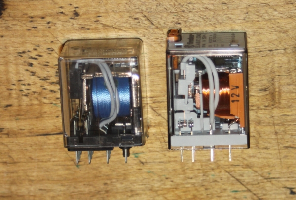
Fujitsu FBR211A DO12-M resp. FBR211A DO24-M 12 or 24 VDC miniature print relays
with their replacement relay Tianbo HJR-4102-L-12V resp. -24V (wash tight) with 'maluska 0316' print on side
RL01, RL03, RL04, RL05 type miniature print relays:
Left side: Fujitsu FBR211-12V, right side Tianbo HJR-4102-L-12V replacement
The transparent top cover of the Fujitsu FBR211 relays is removable (clip on) so you can try your luck with oxide removal spray.
IF Unit (PB-2343)
Did not do this one yet
Read about the RL01 on the IF Unit, what it does and why I have not replaced this one
Note: The RL01 in the IF Unit does not change the actual receivers performance.
Its task is to feed signal levels (S + ALC) to the front panel meters.
As I have no problems with thise signals I did not change this RL01.
Local Unit (PB-2345)
Did not do this one yet
Read about the RL01 on the Local Unit
Note: this relay is for the clarifier. So it does not change the actual receivers performance.
As I have no problems with thise signals I did not change this RL01.
Final Board (PB-2355)
Did not do this one yet
Read about the RL01 on the Final Unit
Note: this relay is said to be replacable without lifting the Final Unit board (the PA board).
Which would be much work since it holds the 3 PA tubes sockets and all.
On my FT-102 this relay is on a little extra piece of PCB
Note: On the 'foxtango.org' website we read the following:
"Yaesu initially placed it there to switch the screen voltage to a lower value when on ten meters for better efficiency.
The relay was inconstant and gave them troubles so they just left it in the radio without switching it on or off. Since they
didn't make the radio with RL01 active for regular production they took it out of the schematic so you will not see it ...()
RL01 on PB-2355 of the FT-102 is for all practical purposes worthless, if it becomes intermittent or problematic just get
rid of it or by pass it. I removed it from my transceiver and the rig is all the more reliable."
see here for full text: http://foxtango.org/FT-102/FT-102%20Relay%20Page.htm
All Data on the Relays
Read about the replacement relays en detail
I did my best to sort the relays listed in an MS Excel sheet
Download the relay table
Meter Lamps
Read about FT.102 Meter Lamp Replacement
These lamps are 12 VDC type, dimensions of the glass body are approx. 3 x 18 mm
This is a half successful replacement, as the new solution provides less luminosity due to my lack in experience
Step 1: The 2 meters have their own sub-chassis. Which is held by two screws accessible from the upper side
after the top cover is lifted (Read the Cautions on top of page before lifting the cover!)
Step 2: Take out Meter Chassis by pulling it backwards carefully, look for
thin wires that are in the way towards VFO tuning knob side
Step 3: Remove the brown tape steadily, flip off the clear plastic cover of the meter
Step 4: Arrange your replacement illumination.
Green silicone hose, cut out original lamp, replacement row of miniature LEDs
We see that mechanically this works fine, the 3 miniature LEDs fit the silicone hose,
BUT ... is hardly bright enough. Sigh.
For replacement I chose 3 mm diameter miniature resistor-LEDs (5V),
green, 13 mA at 5V, 8-20 mcd. I guess 6 x that brightness would be fine.
I measured 12.9 V at the meters pole pins, 15 V for the row of LEDs is also
taking a toll ... maybe 2 LED with right resistor in series would be brighter ...
Things I would like to have done if I only had known before...
• Replace the SO266 PL bushing by a PTFE insulated one, or better a quality N-bushing
• Think of a way to install a BNC bushing for a separate RX antenna
• ... and for separate RX - TX outs for transverter operations
• Find and replace the 'inside PA cage Relay Units RL01 with some more solid, larger contacts relay, 16 A instead of 10 A
• Use brighter LEDs for the Meter Lamps, and do both sides in one go, and same LEDs for same brightness both meters
Finally ...
Though I did not go all the way replacing the relays I am hoping to provide some useful information
how to refurbish the great FT-102. Complex challenges are managed best when viewing the problem from
many aspects or sides. So go thru the other sources linked to on top of the page carefully.


 Attenzione!