-
• Main Page
- • Home
• Antennas - • 1296 MHz
- YBN 23-5mA short Yagi with straight dipole for the 23 cm band
Elevation Plots
- YBN 23-9mA short Yagi with straight dipole for the 23 cm band
Elevation Plots
- GTV 23-14wA 0.94 m bent dipole longyagi for the 23 cm band
Elevation Plots
- GTV 23-23mA bent dipole longyagi for the 23 cm band
Elevation Plots
- GTV 23-25mA bent dipole longyagi for the 23 cm band
Elevation Plots

- GTV 23-34wA bent dipole longyagi for the 23 cm band
Elevation Plots
- GTV 23-46wA 4 m bent dipole longyagi for the 23 cm band
Elevation Plots
- GTV 23-65wA 6.0 m bent dipole longyagi for the 23 cm band
Elevation Plots
- General Info23 cm Yagi building details and background info
-
- YBN 23-5m
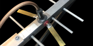
GTV 23-65w Yagi with bent Driven Element
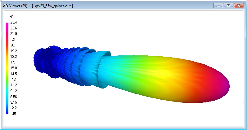
A 6.0 m long 23 cm Yagi that provides a very clean pattern and 23.4 dBi of gain.
With that features she is clearly suitable for single Yagi EME even with modest output power.
The bent DE (K6STI style) transforms from approx. 17 ohms to 50 ohms at feed point.
Design date of issue: 2021.06.05

GTV 23-65w 3D pattern plot at 1296.2 MHz
Performance Data
Specs: with 3.2 mm elements @ 1296.2 MHz
Gain vs. isotr. Rad.  23.4 dBi
Gain vs. Dipole       21.1 dBD
-3 dB E-plane         13.6 deg.
-3 dB H-plane         13.6 deg.
F/B                  -39.3 dB
F/R                  -36.7 dB
Impedance               50 ohms
VSWR Band Width       1.12:1 *
Mechan. Length        5854.0 mm plus 2 x 73 mm offset
Electr. Length        25.3 λ

Stacking Dist. h-pol. (1296.2 MHz)
top-to-bottom         0.98 m or 3.20 ft
side-by-side          0.98 m or 3.20 ft

*) at 1300.0 MHz
How many VHF operators have been looking up this design since May 2021?
Geometry
This Yagi with 3.2 mm elements
|
Ele. 3.2 mm DE 4.0 mm Boom 7.5 x 7.5 mm ABS Plastic Ele. fastening &. photo acc. F4FEY |
|

"Ready to saw and drill" data for mounting elements through this plastic boom:
Coming soon ...
The Drivers diameter is 4 mm.
The EZNEC model is done with Auto-Segmentation at 1296.2 MHz
This Yagi with 3/16 inch = 4.763 mm elements
|
Boom shape: square Boom dim: 5/8 x 5/8 inch Wall thickn.: 1.6 mm Holes in boom: 7.5 mm Offset rear: 70 mm Offset front: 70 mm |
|

"Ready to saw and drill" data for mounting elements through this plastic boom:


The Drivers diameter is 4.763 mm.
The EZNEC model is done with Auto-Segmentation at 1296.2 MHz
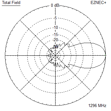
Pattern and VSWR Plots
Elevation and Azimuth plot at 1296.2 MHz


Average Gain corrected Forward Gain is 23.43 dBi or 21.28 dBd.
Return Loss and SWR plots - simulated

Average Gain Correction and G/Ta (T_earth = 320 K, T_sky = 7 K assumed)

Downloads
None so far.
73, Hartmut, DG7YBN