-
• Main Page
- • Home
• Antennas - • 1296 MHz
- YBN 23-5mA short Yagi with straight dipole for the 23 cm band
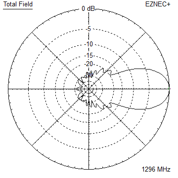
Elevation Plots
- YBN 23-9mA short Yagi with straight dipole for the 23 cm band
Elevation Plots
- GTV 23-14wA 0.94 m bent dipole longyagi for the 23 cm band
Elevation Plots
- GTV 23-23mA bent dipole longyagi for the 23 cm band
Elevation Plots
- GTV 23-25mA bent dipole longyagi for the 23 cm band
Elevation Plots

- GTV 23-34wA bent dipole longyagi for the 23 cm band
Elevation Plots
- GTV 23-46wA 4 m bent dipole longyagi for the 23 cm band
Elevation Plots
- GTV 23-65wA 6.0 m bent dipole longyagi for the 23 cm band
Elevation Plots
- General Info23 cm Yagi building details and background info
-

- YBN 23-5m
General Info on building 23 cm GTV Yagis with bent driven element (K6STI-Style dipole) and background info
Preface: Dear reader
this website may give some insight into how the DG7YBN 23 cm Yagis can be built and disclose some background information of how the models are set up.
Date of issue: 2023.11.10
Correction Factors for Boom and thick Elements?
• Intro
After having measured and published Boom Correction factors for elements for 144 and 432 MHz, verifying the SM5BSZ BC.exe for use on 432 MHz, with some of the Yagi built to these factors breaking several records, I decided to turn to 1296 MHz in order to create a feasible and durable building style to make Low Noise 23 cm Longyagis.
• Handling NEC segmentation and thick wires
It is well known that thick, short elements may produce deviations when being processed in NEC-Kernel driven simulation programs, see here
• Comparing correction values with known works
DL6WU/DJ9BV used similar low segmentation and derived a correction factor of 11.0 mm for element length from NEC model to real build. The correction for my style to built 23 cm Yagis produced around 6 mm in average (SM5BSC's BC.exe takes into account element length and distance to nearer end of boom) so that individual corrections apply per element. Comparing 11 to 6 mm just shows the same basic delta as the well known DL6WU/G3SEK formular shows for elements insulated vs. electrically connected mounted through a same size boom, a ratio of ˜2:1.
• How testing was done and correction values derived
Before designing any long boom Yagi all the theory underwent practical tests for gathering data to derive a coefficient that ensures building Yagi with elements 4.00 mm and 3/16 inch (4.763 mm) through a 15 mm respectively 15.9 mm square boom. A number of 5 ele. YBN 23-5m were built on plastic boom, aluminium booms (tnx Pawel, SQ5ESM and John, ZS6JON) with larger rear and front offset to minimise the effect on elements near boom ends and when that was done with shorter offsets. Understanding how the SM5BSZ BC.exe code works and what the single parameters account for, enables a thoughful step-by-step approach to get the factor right with ZS6JON's Anritsu MS2000 being a worthy VNA that produces fine Return Loss plots and Smith Charts of the test antennas to compare with the simulations.
Then all was repeated using the 9 ele. YBN 23-9m (tnx Jon, ZS6JON). Only after we found reasonable confirmation we turned towards pubishing and producing the first Longyagis.
All steps important steps and charts are layed down in bilingual publications in the Dubus Magazine:
A 1296 MHz Low Noise Yagi with a Bent Dipole
A GTV 70-25m scaled to 23 cm including detailed building instructions.
Applied Conversion of Segmented Wires from NEC2 to 1296 MHz Yagi Elements
Insulated through Boom BC based on SM5BSz's BC.exe with a fixed offset for 1296 MHz in interaction with the models segmentation density.
Both Dubus 2/2021 ... with SQ5ESM and ZS6JON
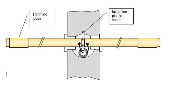
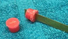
All of the test Yagis carried tuning tubes on the dipole as to be seen on image below to tune to the true frequency i.e. lowest peak in Return Loss handling the challenge to connect to split coax very short and possible effects of feeding the dipole arms through a metal boom.

fixed offset at being out of specs for boom and element diameter.


Mounting Elements
Any DG7YBN Yagi with Geometry Table refering to elements mounted insulated through the boom:
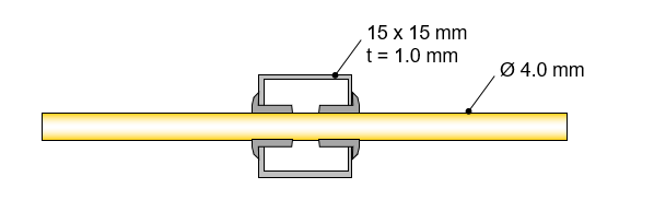
• Boom 15 mm square, wall thickness 1.0 mm, elements 4.0 mm, holes in boom 6.0 mm, insulator length 7 mm:
Use SM5BSZ BC.exe(*) + a fix offset of 2.21 mm

• Boom 5/8" square, wall thickness 1.6 mm, elements 3/16", holes in boom 7.50 mm, insulator length 7 mm:
Use SM5BSZ BC.exe(*) + a fix offset off 4.52 mm
Notes:
• Segmentation of model in NEC2 (Ref.: Nec2dXS Kernel as in EZNEC) with Auto Segmentation in Conservative Mode.
• *: BC.exe without Check-Functions for Boom Diameter, Element Diameter etc.
Numbers do not represent pure Boom Correction. All deviation from NEC running elements with very short and thick segments, BC.exe running far from coefficients gathered at 144 MHz by SM5BSC are enclosed, as well as all factors were derived from measuring complete Yagis set up as described. The benefit of proceeding so is that the Yagis show a close matching frequency answer when build this way. The downside is that unless more variations of boom sizes and element diameters are tested no general formula for boom correction or overall factors can be derived.
Any design done with 4.00 mm elements may also be suitable to mount elements
conductive through a boom 15 x 15 mm (press fit):

DL6WU/DJ9BV boom correction may apply:
1296 MHz : add +11.0 mm
For further read see here
Dipole
• Schematics
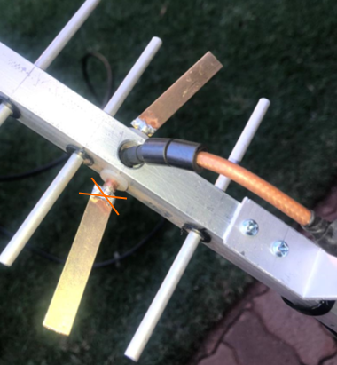
Straight dipole

Bent driven element (K6STI-Style dipole)
Straight inner pieces of dipole are copper wire of diameter ~5 mm,
slotted on outside ends to hold the sheet metal pieces that make the arms.
• Dipole arms dimensions: approx. 40(x) x 7 mm cut from at = 0.5 mm brass sheet
x: exact length is subject to which design is choosen and how long inevitable coax pigtails will be.
 The insulators holding the dipole straight rods may be made from PTFE or
other suitable heat resisting and firm plastic as coax and dipole arms
need to be soldered onto the rods.
• Downside of boom with hole for soldering.

• Upper Side of boom with hole for feeding the coax into the boom
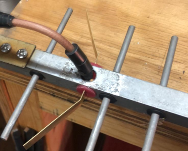
Do NOT solder the dipole arms to the inner straight pieces until sealed,
as sealant may affect the fine tuning.
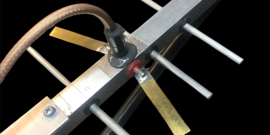
Photo Credit: ZS6JON
Seal with suitable paste, no cheap silicone,
choose a water resistant hardening paste with low permittivity.
We took Spinner PLAST 2000 for all the ZS-built Yagis.
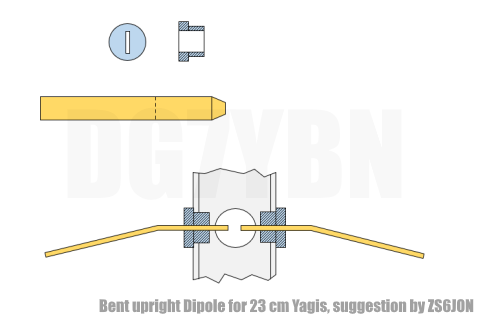
Upright bent Dipole (K6STI-style):
The holding brackets will have to be slotted, maybe to be printed in 3D.
Feed
• 3/4 lambda coax line with ferrite cores for symmetrizing

Important: Choose suitable size for first ferrite to feed into the hole
• Bridge arrangement for trimming the line on a VNA

Calibrate to transmission mode with brigde, then add the coax stub including ferrites, flange connector and bracket.
Trim to 432.1 MHz as the 1296 MHz 3/4 lambda line will clearest show as 1/4 lambda stub on 432.1 MHz.


• Make the bracket for the flange connector in a way that it can serve as a holder for the feed coax and allows to feed in the coax from the rear to least disturb the driver cell.
Additional Notes
• Scaling Yagis from an other band to 23 cm with much increase in element diameter?
What I do is not a simple scaling, which would lead to funny element diameters (like 1.33 mm for a 432 MHz Yagi with 4 mm elements). After scaling in EZNEC the length of each element is carefully adapted to the new element diameter by hand, element after element one by one, with key parameters forward gain, F/B and impedance not only at operation frequency monitored. Whenever necessary, slight adaptions of element positions are carried out. The finished adaption to 23 cm then is nearly equal to the 70 cm or 2 m version. Gain does not rise though elements are thicker as prime focus was on a reproducable real world build.
Let us compare ...
1. 144 MHz Model GTV 2-14w, 8 mm elements and 1296 MHz GTV 23-14w, 3.2 mm elements

2. 432 MHz Model GTV 70-25m, 8 mm elements and 1296 MHz GTV 23-25m, 3/16 inch (4.763 mm) elements

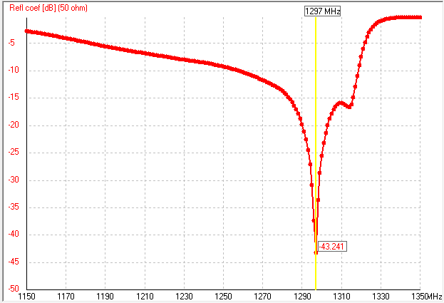
Comparing S11 - Return Loss in dB for a scaled model from 70 cm to 23 cm and real plot of the 23 cm Yagi.
70 cm Yagi GTV 70-46w:
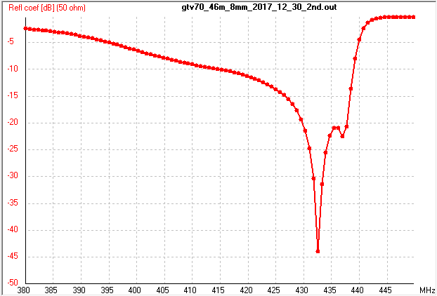
23 cm Yagi GTV 23-46w scaled from the GTV 70-46w:
23 cm Yagi GTV 23-46w real builts plot:

Mind that building a Yagi with close results to simulated specs is not a question of using NEC2, NEC4, NEC5 or miniNEC kernel in simulation but of using carefully measured correction values. With such one can make Yagis with thick elements or low ratio between element length and boom thickness if only the correction factor is procuded the right way.
I wrote these notes partly because I read some funny reviews regarding my 23 cm Yagi designs.
Now I hope much is clearer and only wish to add that maybe 'a fool believes that everyone else is a fool too'.
73, Hartmut, DG7YBN