-
• Main Page
- • Home • Building
-
- Boom CorrectionIntro to Boom Correction and complete Collection of Factors

• DL6WU / G3SEK formulas and charts in detail
• DJ9BV insulated through boom
• I0JXX insulated through boom
• K1FO insulated through boom
• VE7BQH Cushcraft & Cudee on Boom
• DG7YBN semi-insulated on Boom
• Intro to SM5BSZ's BC.exe
• Segmentation Issues and more ... - Symm. & BalunsSymmetrising Devices from Sleeve Balun, F9FT Tube, EMI, G0KSC, Pawsey, 50 ohms Quarter Wave Line to 12.5 and 28 ohms DK7ZB Match ... plus Test Equipment - the RF Current Meter
- Phasing & Matching LinesHow to measure coax stub lines, produce coaxial impedance transformation lines, Baluns and how to stack and match with coax lines
- Feeding XPOL YagisCircular Polarisation explained and how to feed xpol Yagis
- Howto - Bent DEHow to bent a GTV Yagi DE with a simple selfmade tool:
Bending aluminium tubes by hand leads to buckles and brocken tubes. So I show what a simple selfmade tool looks like. You will need just a piece of wood, a few minutes and a jigsaw to produce one.
It will make the job much easier.
DIY - Bending Tool

- Building a YagiA collection of building hints - from DE-Box to bending Support Struts and mounting Elements. - Under Construction -
- Boom StrutsA collection of building hints - Planning and bending Support Struts and making bending tools. - Under Construction -
- Scaling Yagi ElementsHow to scale complet Yagis in Frequency and Element diameters from one dimension to another by hand
- Boom Correction
Circular Polarisation for xpol Yagis
What makes a circular polarised Yagi?
Usually two identical single polarisation Yagi-Uda antennas are being set up for 90 deg. of polarisation difference.Further these two antennas are excited with a 90 deg. of phase shift. With this now a rotating field is radiated.
Depending on the sense of rotation this can either be rotating clockwise (Left Hand Polarisation) or counter clock
wise (Right Hand Polarisation). Terminology is as following: the wave is being radiated from the source,
we follow the wave spreading which for the Yagi-Uda is of relevance in beam direction.
Chapters added or revised in June 2023:
• Definition Handedness RHCP / LHCP
• The Marvels of the Univers
• Two Stations with Circular Polarised Antennas?
• Coax Length Calculator
Right Hand Circular Polarisation (RHCP)
RHCP is clockwise looking in beam direction* (red = connected to core of coax)(1) vertical plane first

(2) horizontal plane first

Left Hand Circular Polarisation (LHCP)
LHCP is counter clockwise looking in beam direction* (red = connected to core of coax)(1) vertical plane first
(2) horizontal plane first

How to read these drawings
Red arms of dipoles are where to coax core gets attached to ('hot side').
Grey ones are connected to the shield / braid side.
Looking from the reflector forward ... into wave propagation direction when transmitting
the first dipole sends out a wave, we start at phase 0 deg., the second dipoles wave meets the
first dipoles one when that is a 90 deg. already.
Without geometrical shift, both dipoles in same plane:
Horizontal dipole fed straight (core on upper side), vertical dipole (core on right side) thru the 1/4 lambda (90 phase lag) coax results in LHCP.
Horizontal dipole fed through a 1/4 lambda coax (90 phase lag)(core on right side) straight, vertical dipole fed straight results in RHCP.
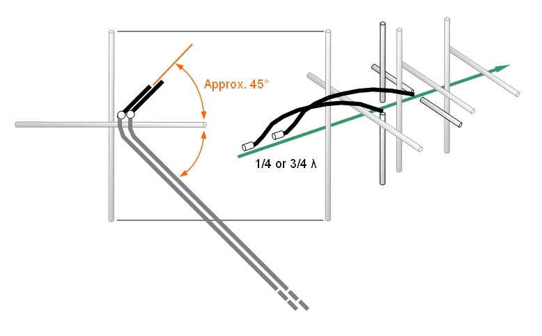
At a straight geometrical shift of 1/4 λ = 90° the necessary phase shift is achieved by the
mechanical built alone. The opposite extreme is with both antennas without any geometrical
shift. Here the necessary degrees of phase shift has to be introduced with a 1/4 λ = 90°
of extra feedline coax length that adds the missing runtime to feed one plane.
The other dipole must be excited in a way that the first dipoles wave meets the other dipoles wave
when it has travelled 90° already.
• Introducing 180° (1/2 λ) instead of the 90° (1/4 λ) makes just a reversal of hands.
Steps towards a circular polarised Yagi


"The sense of rotation of the extremity of E describing a circle or an ellipse in the plane of polarization (perpendicular to the direction of propagation) is called the sense of polarization, or handedness. This sense is called right handed (left handed) if the direction of rotation is clockwise (counterclockwise) for an observer looking in the direction of propagation"
Definition ‘direction of propagation’:
Dr. N. K. Nikolova, Professor, Canada Research Chair in High-frequency Electromagnetics, McMaster University, Hamiltion, Canada
see here: https://www.ece.mcmaster.ca/faculty/nikolova/antenna_dload/current_lectures/L05_Polar.pdf
Chapter 5. Antenna Polarization, pg. 11:
"By convention, the antenna polarization is defined by the polarization vector of the wave it transmits."
As spin direction or handedness depends on the point of view in beam direction transmitting, a definition or application example that does not hold the view point is worthless as the handedness swaps between transmit and receive for circular polarisation.


• In case the phase lag is not 90 deg. sharp, its not circular but elliptical.
• The ellipse flattens out towards a phase lag of 45 degrees.
• In case the phase lag is 45 deg. it might be linear vertically or horzontally if the Cross Yagi is mounted in "X",
• Else still linear but at 45 deg. or 135 deg. to the horizon and named slant polarisation,
• A circular polarised antenna with RHCP in case of transmitting will receive LHCP and vice versa,
• A circular polarised antenna with RHCP in case of transmitting in beam direction will radiate LHCP to the rear and vice versa.
The Marvels of the Univers
How on earth ... why do we encounter so many diverging plans for phasing RHCP / LHCP?I am close to conclude that we have a case of common wisdom regarding the handedness of circular polarisation in which everyone is on the wrong hand, which is fine for all then ... except for the ones who seek to put up a theory.

After having read most every publication and website about the topic of what in common sense is RHCP and LHCP I could not come to a final conclusion. Below I have listed a handful of published examples and my interpretation of these regarding the handedness of these according the official definitions as shown above.
In case I am doing a wrong, any constructive feedback is welcome.
| • RSGB VHF/UHF Manual, G.R. Jessop, G6JP, 4th edition 8.26 Fig. 64 General arrangement of feeders with delay line (phasing) of clockwise radiation ... is about the only publication, which has it as I think it must be. | ||
|---|---|---|
 Image: RSGB VHF/UHF Manual, G.R. Jessop, G6JP, 4th edition 8.26 Fig. 64 |
My interpretation: This Yagi transmits RH and receives LH
|
|
| • DK7ZB website: | ||
|---|---|---|
 Image: M. Steyer, DK7ZB website, "Cross-Yagi", Circuit for right-hand circular polarisation (RHCP). Orange lines and comment aded by DG7YBN (propagation on tx into the board). |
My interpretation: This Yagi transmits LH and receives RH 
|
|
| • SV1BSX website: | ||
|---|---|---|
 Image: SV1BSX, https://www.qsl.net/sv1bsx/antenna-pol/polarization.html |
My interpretation What is drawn here as spin rotation spiral is turning against the clock, it is CCW. This Yagi transmits LH and receives RH 
|
|
| • WA9PYH in QST magazine: | ||
|---|---|---|
|
WA9PYH in QST issue May 2010, Circularly Polarized Yagi Antennas for Satellite Communications https://www.arrl.org/shop/files/pdfs/Satellite%20project.pdf 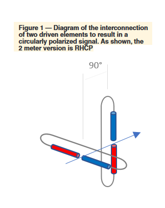 |
My interpretation: This Yagi transmits LHCP and receives RHCP. 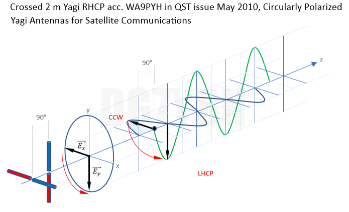
|
|
Two Stations with Circular Polarised Antennas?
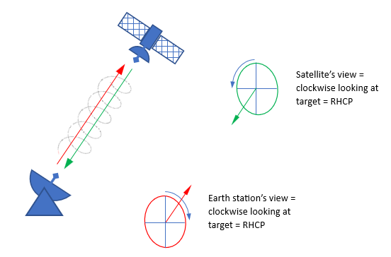
A common simple image is a long threaded bolt as wave path and the two antennas being nuts on either side of the same hand threaded bolt. It does not matter of receiving or transmitting is taken into account. Transmitting is like screwing in while receiving is like screwing out. Any CP antenna transmits on one handedness and receives on the opposite handedness. Hence a CP Yagi at station (A) that transmits RH will receive LH from station (B) which from their operators point of view transmits RH.
This said, there might be extreme propagations with low above the horizon satellites were the circular hand is inverted at times by being reflected at layers in the atomsphere
Discourse: Some will read the above and think of it as nonsense. As what is sent as RHCP will screw into the receiving antenna as ( ... if it would be : Authors note) LHCP. Which is truely turning counterclockwise in the view of the receiver. But is there a dissent? Any screw, we may look at a right threaded one, can be screwed into a nut and out again. For screwing it in we turn it clockwise. For unscrewing it we turn it counterclockwise. It just stays a right handed thread. The IEE's definition points out that the 'handness' shall be determind into direction of wave propagation.
How many radio enthusiasts have been looking up this website since July 2016?
Basics: Unit Circle and Wavelength λ

90 deg. is just 1/4 λ. Any multiple of 90 deg. makes a multiple of 1/4 λ.
From 360 deg. on the circle starts again.
Any 360 deg. + x deg. is same as just x degrees because of the periodicity of sinus and cosinus.
That is why 450 deg. (if that would exist) makes just 90 deg. or 1/4 λ.
Offset between Polarisation Planes
Most xpol Yagis have an offset between their polarisation planes (on left). If not, we call them COPLANAR (on right).
If you only operate either horizontal or vertical polarisation at a time the offset of dipoles on boom and feedline lengths ar no issue at all.
Feeding a Yagi that has a geometrical offset between the planes of 90 degrees with equal phases from equal lengths of coax makes
a fine circular polarisation (left hand here) since the needed shift is 'built in'.
Feeding one dipole in the coplanar arrangement (on right) with a phase lag of 90 degrees by prolonging its feedline by 1/4 λ makes a fine circular polarisation as well.

What if the geometrical built does not meet one of the extremes 0 or 90 deg.?
Maybe the antenna designer took care of a sensitive spacing between the two planes sets of elements
and we find a spacing that is not nill and not electrically 90°. What to do now?

If we shift the two planes dipoles from zero to 360° phase we get the whole spectrum of polarisation.
From 360° onwards it all starts anew because of the periodicity of the sinus wave.
RHCP and LHCP are just stations on the way from linear to elliptical to orthogonal linear polarization at half way (180 deg.) and further on to complete the circle or one wavelength at 360 degrees. Simply put if you do not meet the phase difference between the dipoles of your Yagi exactly, you do not end up with nothing. You will have a slightly elliptical polarization then.
In case you like to learn more the keywords are "Poynting vector" and "Poincaré spere"
s. Kraus, J. D.: Antennas, 2-35 Wave polarization and the Poynting vector, Fig. 2-37, Second Edition 1988, McGraw-Hill
s. Kraus, J. D.: Antennas, 2-36 Wave polarization and the Poincaré spere, Fig. 2-40, Second Edition 1988, McGraw-Hill

I have set up a chart holding the phase difference as a sinus wave:


Calculate the extra length of coax feeding
the other dipole for circular polarisation
Notes:
• The calculator gives a negaive length ... ?
Negative lengths for the extra coax occure from a geometrical distance larger 1/4 λ on ...Which means that the leading dipole is ahead in phase by larger 90 degrees by its geometrical distance to the rear dipole. So the rear dipole needs to catch up to 90 degrees. For this we shorten its supply coax by the given length, so it is fed earlier.
An example by numbers If for example the distance of dipoles is 200 mm for a 435 MHz xpol Yagi, lambda is 689 mm, 1/4 lambda = 90 deg. is 172 mm. What we find as phase between the two dipoles is 104.5 degrees.
The needed phase lag of 90 degrees is overshot by 14.5 degrees or 200 mm - 172 mm = 27.7 mm already.
• Example with coax v-factor:
Complete feed and phasing lines for a 50 ohms 435 MHz xpol-Yagi, 50 ohms lines from PE coax.
with 200 mm offset between the element planes: We shorten the coax for the rear dipole by 14.5 degrees or 27.7 mm x 0.66 = 18.3 mm (RG 213 with v-factor = 0.66) so that it 'catches up' to meet 90 degrees between the dipoles when radiating.

• Frequency dependancy of plastics: velocity factor adaption for VHF / UHF
As explained on the 'Phasing & Matching' website the v-factor of plastics, here the inner coax insulationis given at 1 MHz. For VHF/UHF it has higher numbers. A rule of thumb is to shorten results based on the 1 MHz
numbers by 7 percent for PE, 5 percent for PTFE coax, less for air foam coax.
A trim on the VNA is better than just cutting by rule of thumb, see here
LMR 240 has same v-factor as LMR240UF
LMR 400 has same v-factor as LMR400UF
Phasing xpol Yagis for map65
There are 2 sources I pulled knowledge from. The prolific Rainer Bertelsmaier, DJ9BV and Leif Åsbrink, SM5BSZ have set up schemes
how to phase and feed xpol Yagis in the late 1990ths. I do recommend to read both, especially SM5BSZ's notes on the benefits of X instead
of + configuration of the Yagi, before you set to works.
DJ9BV, Switchable Polarisiation For Cross Yagis, Dubus 1/1996
SM 5 BSZ - Simple Polarisation Switching, link to website
SM 5 BSZ - Separate Polarisation Switching for Rx and Tx, link to website
Most operators will set up the + configuration as they want to use a clear hpol when working tropo with their array.
This is the first kink in the complexe matters of phasing xpol Yagis. Because it is clearly possible to get hpol and vpol polarisation
using the X - configuration. SM5BSZ shows how
However, the 'modern' approach in majority will be TXing either RHCP or LHCP constantly, so you can be heared worst -3 dB whatever Faraday Rotation
is up or not. And feed the RX lines to either switchable hpol / vpol or dual receiver system. Which might be followed by a map65 dual channel decode
software.
So I show a simple coax wiring for use of a dual receiver setup.
If you do not run a map65 and dual channel sound card etc. you can use two separate radios and PCs running 2 WSJT programs,
or have a manual switch to chose between the RX coaxes leading to a single receiver.
Phasing xpol Yagis for map65

Phasing xpol Yagis for map65 with abilty to transmit RHCP and LHCP
That does include the coax relays, connectors, everthing. This might be acheived by measuring the ready made ensambe with a VNA.
You will get a resonate spot at some frequency corresponding with the ensemble as if being a 1/4 λ stub. Now dress the (2)
coax to be same.
Find hints for measuring a coax stub resonance here
Leading the Feedlines
How to lead the feeding coax lines for least interference with the Yagi's structure
Sample Builds
GTV 2-8w XPOL by DJ4TC, coax feedlines to come in from the rear

The geomatrical shift between planes is 80 mm or 13.8 degrees of phase on 144.1 MHz. For driving that Yagi with
a Circular Polarisation need to prolong on of the feeding coax lines by 76.2 degrees to make the full 90 degrees.
With a H2010 coax (v-factor at 1 MHz = 0.83) we need to prolong one planes feed line by 365 mm.
Taking onto account that that v-factor growns with frequency and is around 5 percent lower at 144 MHz than on 1 MHz
we end up with a needed length of 348 mm.
But yet again, be adivised to measure the length yourself if you have a VNA at hand:
76.2 degrees of 144 MHz is (144 / 76.2 x 100) = 188.9 MHz to trim to for being resonate as a Quarterwave Stub ...
73, Hartmut, DG7YBN