YBN 28-4w with straight split Dipole
Digi Modes + SSB band 28.0 to 29.2 MHz
A compact 10 m Yagi on 4.0 m boom (plus mounting offsets) that covers 28.0 - 29.1 MHz with a VSWR < 1.15.
The design conception is such that the Sirio SY 27-4 can be used as a hardware base. Its Gamma Match is dismissed then.
This Yagis feedpoint impedance is 50 ohms.
In the following geometry data for building with 16 mm tube elements and with taper scheme acc. the Sirio SY 27-4 hardware 16, 12, 8 mm are on display.
Design date of issue: 2021.11.16
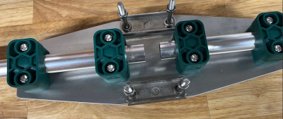
Mind that if you like to modify an existing Sirio you need to build a new dipole holder plate that separates the two arms.
YBN 28-4w built by Frank, PA2DKW for a field day

The SWR curve was totally perfect from the first start!"
Plotted 9 m AGL w. nanoVNA-F, span 26.0 - 30.0 MHz, VSWR, Return Loss (S11), Smith Chart:

Build details: Rectangular U-Bolts holding aluminium plates on boom, hydraulic clamps
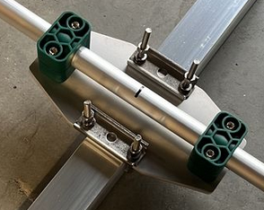
Geometry for building with elements in hydraulic clamps, insulated above boom:

YBN 28-4w and YBN 50-5wrc built by Karel, OK2ZI at use on DXpedition TN8K

Find a PDF with geometry and taper scheme for transport on flights below.
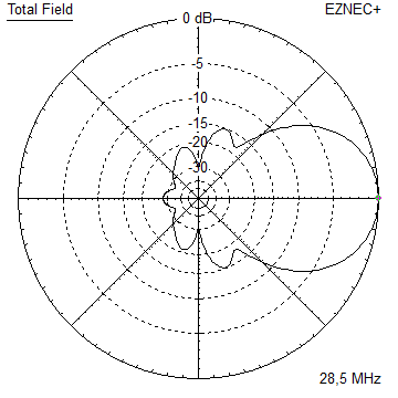
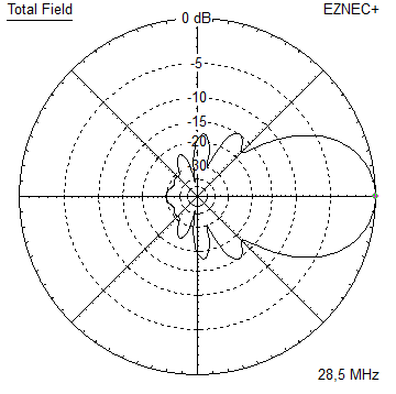
Current distribution
All ele. 16 mm version:
All ele. tapered 16, 12, 8 mm version:
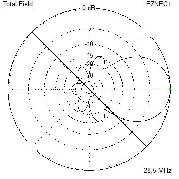
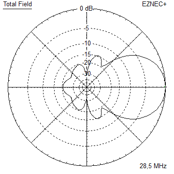
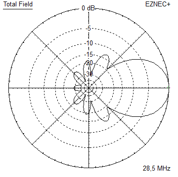
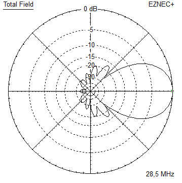
Performance Data (28.5 MHz, el. 16 mm)
Gain vs. isotr. Rad.   8.26 dBi
Gain vs. Dipole        6.1 dBD
-3 dB E-plane         62.6 deg.
-3 dB H-plane         98.6 deg.
F/B                  -20.2 dB
F/R                  -12.6 dB
Impedance               50 ohms
Mechan. Length        4000 mm
Electr. Length        0.38 λ

Stacking Dist. h-pol. (28.5 MHz)
top-to-bottom          approx. 8 m
side-by-side           approx. 6.5 m
Geometry
For building on a 40-50 mm boom, 16 mm elements insulated with hydraulic clamps like from co. Stauff:

Flight pack DXpedition taper version, no element nor boom section longer than 1.40 m:
How many pageviews did this design get since late Dec. 2021?
Pattern and VSWR Plots
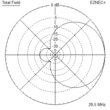
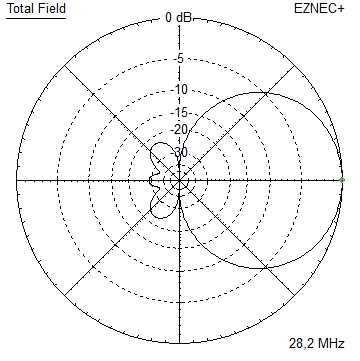
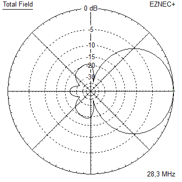
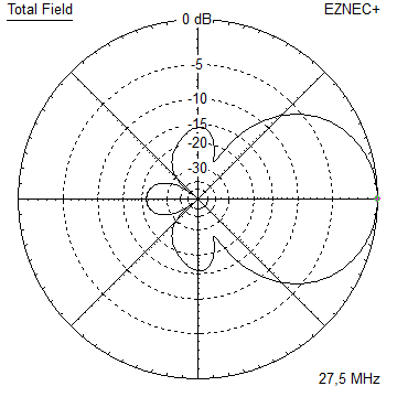
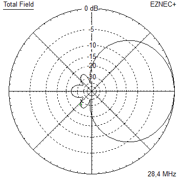
Elevation and Azimuth plot at 28.5 MHz


SWR and Return Loss plots - simulated with 4nec2


Radiation pattern with Ground Gain
At 12 m above perfect ground

Gain vs. isotr. Rad.  14.1 dBi at  12 deg.
Gain vs. Dipole       12.0 dBD
Gain vs. isotr. Rad.  12.4 dBi at  40 deg.
F/B                  -19.6 dB  at 167 deg.
At 17 m above perfect ground

Gain vs. isotr. Rad.  14.2 dBi at   9 deg.
Gain vs. Dipole       12.1 dBD
Gain vs. isotr. Rad.  13.4 dBi at  27 deg.
Gain vs. isotr. Rad.  11.3 dBi at  50 deg.
F/B                  -19.2 dB  at 171 deg.
Stacking

The ordinary stacking elevtion pattern is not so great regarding the rear side.
Please take a look at the 'special stacking' and see how to easily obtain a cleaner rear pattern.
Elevation plot and data of 6 over 6 array at 10.1 m stacking distance:
Lower Yagi 11 m, upper Yagi 18.0 m above perfect gnd

Gain vs. isotr. Rad.  16.6 dBi at  10 deg.
Gain vs. Dipole       14.5 dBD
F/B                  -15.2 dB  at 170 deg.
Special Stacking
The following two arrays enclose elements of a technique introduced by Justin Johnson, G0KSC in
"Enhancing the Stacked Yagi with the Addition of Z Axis Parasitic Elements", Dubus 2/2017 and Dubus Technik XVI
Read more about his in the article preview as a PDF on the G0KSC website: https://www.g0ksc.co.uk/G0KSC217.pdf
Stack of 2 Yagis with extra reflector, upper Yagi is 2620 mm forward:
Elevation plot and data of 4 over 4 array at 11.0 m and 18.0 m = stacking distance 7 m

The extra reflector is a 16 mm tube, l = 5304 mm.
It is mounted on half height between the Yagis and in same position as the regular reflectors.

Gain vs. isotr. Rad.  16.8 dBi at 10 deg.
Gain vs. Dipole       14.7 dBD
F/B                  -27.4 dB  at 170 deg.
Stack of 3 Yagis with extra reflector, upper Yagi is 2620 mm forward:
Elevation plot and data of 4 over 4 over 4 array at 10.0 m, 17.0 m and 24.0 m = stacking distance 7 m

The extra reflectors are 16 mm tubes, l = 5304 mm.
They are mounted on half height between the Yagis and in same position as the regular reflectors.


Stagger Stack of 2 Yagis, upper Yagi is 2620 mm forward:
Elevation plot and data of 4 over 4 array at 11.0 m and 18.0 m = stacking distance 7 m

Gain vs. isotr. Rad.  13.97 dBi
Gain vs. Dipole       11.82 dBD
F/B                  -24.7 dB
73, Hartmut, DG7YBN
