-
• Main Page
- • Home
• Antennas - • 10.1 MHz
- • 14 MHz
- • 18 MHz
- • 24.9 MHz
- • 28 MHz
- YBN 28-4wA 4.0 m long 28 MHz 4 ele. straight split Dipole to be very uncritical for home building.
Elevation Plot
- YBN 28-5wA 7.6 m long 28 MHz 5 ele. straight split Dipole to be very uncritical for home building. A wideband version with hugh bandwidth and yet high F/B.
Elevation Plot
- YBN 28-5LA 8.3 m long 28 MHz 5 ele. straight split Dipole to be very uncritical for home building.
Elevation Plot
- YBN 28-6nA 9.6 m long 28 MHz 6 ele. straight split Dipole to be very uncritical for home building.
Elevation Plot
- YBN 28-7mA 13.9 m long 28 MHz 7 ele. straight split Dipole to be very uncritical for home building.
Elevation Plot
- YBN 28-7wA 13.6 m long 28 MHz 7 ele. straight split Dipole to be very uncritical for home building.
Elevation Plot
- YBN 28-8mA 17.2 m long 28 MHz 8 ele. straight split Dipole
Elevation Plot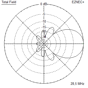
- GTV 28-4wA 5.2 m long 28 MHz 4 ele. with bent Dipole.
Elevation Plot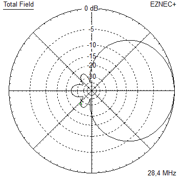
- GTV 28-7wA 13.7 m long 28 MHz 7 ele. with bent Dipole.
Elevation Plot
- GTV 28-9wA 20 m long 28 MHz 9 ele. with bent Dipole.
Elevation Plot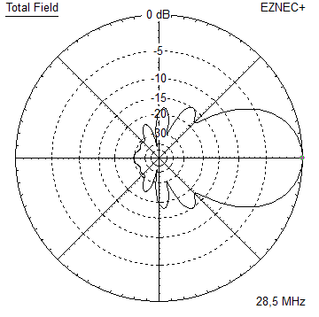
- GTV 28-9m LTA 23 m long 28 MHz 9 ele. with bent Dipole.
Elevation Plot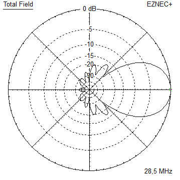
- YBN 28-4w
- • 50 MHz
- • 70 MHz
YBN 28-7m with straight split Dipole
Digi Modes + SSB band 28.0 to 28.7 MHz
On 28 MHz we should less look for gain but very clean directivity, because if the band is open successful DX more or less comes down to fade out unwanted signals. If we can easily produce a signal that enables us to ping our own echo when twice (!) around the globe with less than 100 watts of output, we may pass on 0.5 dB gain. And when band is closed that little bit would not help at all.
The patterns scattering factor (dt.: Streufaktor) as ratio of all rear and side lobes against the beam lobe is what we should look for in first place.
Design date of issue: 2020.10.03
YBN 28-7m by IZ1RFT


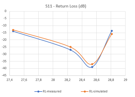
VSWR measurments with a RigExpert AA-35:
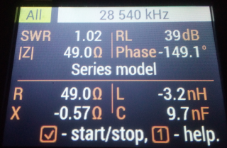

Photo Credit: IZ1RFT. Tnx Matteo!
Matteo reports:
2022-06-12:
"Last Sunday evening at 11.00 pm local time with dg7ybn 7 element yagi I made a deep impact. I was the only station from Europe that arrived so strongly in the South Pacific long path. I connected all areas of Australia, all areas of Nee Zealand and 2 stations from new Caledonia and also mobile stations from VK and ZL. What a show 10 meters is the most beautiful band and your 7 element Yagi is a killer."
2022-11-12:
"Hi Hartmut: this morning JA long path 59 + 25 ... scary, dg7ybn yagi 7 is a cannon."
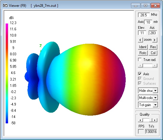
Current distribution

Performance Data (28.5 MHz, 16 mm el.)
Gain vs. isotr. Rad.  12.3 dBi
Gain vs. Dipole       10.2 dBD
-3 dB E-plane         44.4 deg.
-3 dB H-plane         52.0 deg.
F/B                  -26.3 dB
F/R                  -21.0 dB
Impedance               50 ohms
Mechan. Length       13869 mm
Electr. Length        1.32 λ

Stacking Dist. h-pol. (28.5 MHz)
top-to-bottom          12.0 m   or   39.4 ft
side-by-side           13.9 m   or   45.7 ft
Geometry
For building on a 40-50 mm boom, 16 mm elements insulated with hydraulic clamps like from co. Stauff:

IZ1RFT's build: Element and dipole holders, not the spacers for the quarterwave line
![]()
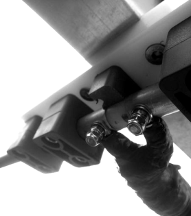
Dipole holder and feed with quarterwave line (LCF 12-50) to boom with ferrite cores added:

Photo Credit: IZ1RFT. Tnx Matteo!
Sletch of IZ1RFT's boom:

How many pageviews did this design get since Oct. 2020?
Pattern and VSWR Plots
Elevation and Azimuth plot at 28.5 MHz


SWR and Return Loss plots - simulated with 4nec2

Radiation pattern with Ground Gain
At 12 m above perfect ground

Gain vs. isotr. Rad.  17.8 dBi  at  12 deg.
Gain vs. Dipole       15.7 dBD
F/B                  -25.2 dB   at 168 deg.
At 20 m above perfect ground

Gain vs. isotr. Rad.  18.1 dBi  at   7 deg.
Gain vs. Dipole       16.0 dBD
F/B                  -26.1 dB   at 172 deg.
Stacking

Elevation plot and data of 7 over 7 array at 12.0 m stacking distance
Gain vs. isotr. Rad.  15.27 dBi
Gain vs. Dipole       13.12 dBD
F/B                  -29.1 dB
Elevation plot and data of 7 over 7 array at 12.0 m stacking distance:
Lower Yagi 12 m, upper Yagi 24 m above perfect gnd

Gain vs. isotr. Rad.  19.99 dBi at   7 deg.
F/B                  -28.31 dB  at 173 deg.
73, Hartmut, DG7YBN