GTV 50-10LT with bent Driven Element
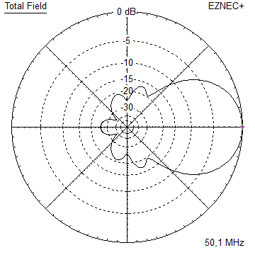
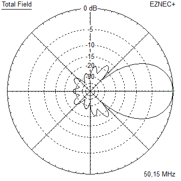
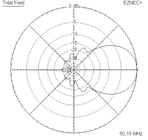
This Longyagi has a high F/B and altogether very little back lobe volume
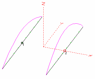
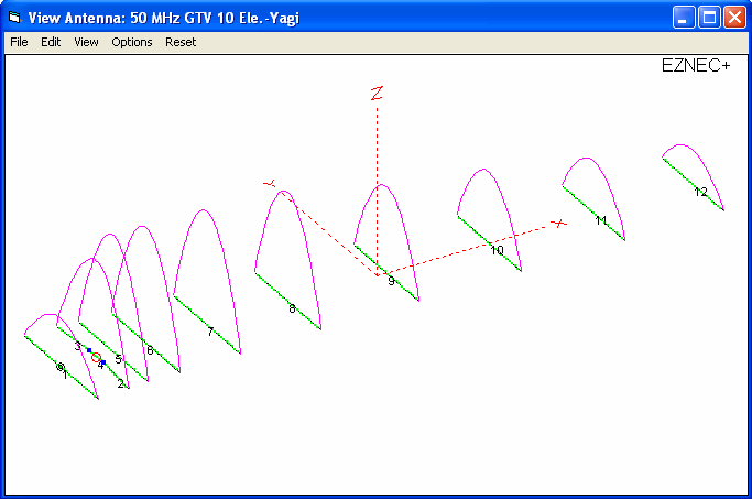
The bent DE (K6STI style) transforms from low impedance to 50 ohms at feed point for direct feed.
The name "LT" reminds of the EF0210LT by YU7EF. This design here has slightly higher Antenna Temperature only
but more gain.
A serious DX and EME Long Yagi that will deliver even in very difficult RX situatons.
|

|
Performance Data
Gain vs. isotr. Rad.  14.5 dBi
Gain vs. Dipole       12.4 dBD
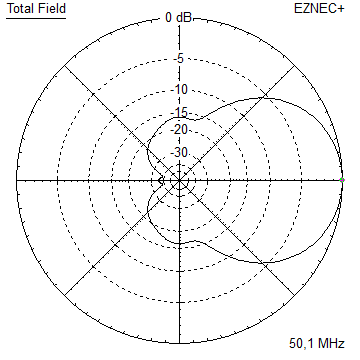
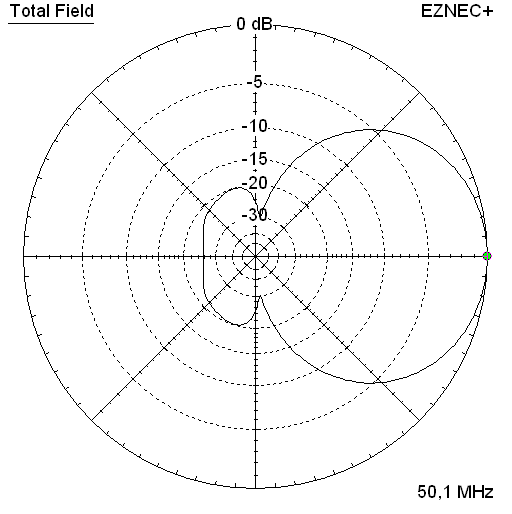
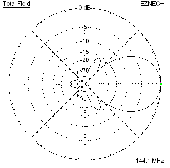
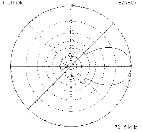
-3 dB E-plane         36.0 deg.
-3 dB H-plane         39.4 deg.
F/B                  -28.1 dB
F/R                  -26.0 dB
Impedance               50 ohms
Mechan. Length      14,550 mm
Electr. Length        2.43 λ
Geometry

The Drivers diameter is 3/4 inch, elements are 5/8 inch
            Refl      DE      D1      D2      D3      D4      D5      D6      D7      D8
Pos.           0     820    1207    1954    3365    5220    7500    9856   12266   14550
Ele.        2952    2868    2772    2748    2680    2637    2586    2568    2514    2458
Diam.        5/8     3/4     5/8     5/8     5/8     5/8     5/8     5/8     5/8     5/8
Difference between simulation using high segmentation as given above and low segmentation per "Auto Segmentation" at 50.15 MHz
makes a delta of 0.1 MHz. With 16 mm per MHz on 50 MHz we need to add 1.6 mm to the ele. lengths in this table to compensate the SBC.
Now we add the common BC on top of that and build a Yagi that is on correct frequency.
BC? .. really depends on way of fastening elements. For any as low as approx. 3 mm on-boom holders at 40 mm
square boom this is around 7 mm on 50 MHz. Of coarse drastucally reduced using higher not too wide holders
or round boom tubes. Call in if you want to build this Yagi and I see how I can help sorting
the boom correction with you.
Boom? For making a 'lightweigth version' the boom could be 'tapered' from square tube
1 x 4.7 m long 50 x 50 x 5 mm mid section
2 x 3.0 m 40 x 40 x 5 inter section plus 0.15 mm insertion length
2 x 2.0 m 30 x 30 x 4 mm outer parts plus 0.15 mm insertion length
plus adding a bit of supporting ropes as shown on my Building Pages here
Bent Dipole?

Pattern and VSWR Plots
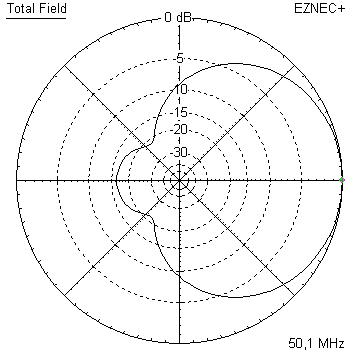
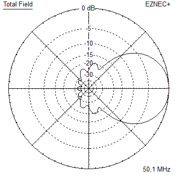
Elevation and Azimuth plot at 50.15 MHz


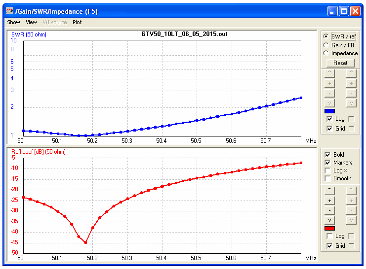
RL and SWR plot - simulated
Downloads
EZNEC file of this Yagi (5/8 in ele.)
73, Hartmut, DG7YBN
