-
• Main Page
- • Home
- • 40 MHz
- • 50 MHz
- YBN 50-2wA 1.2 m 50 MHz 2 ele. with split Dipole for direct 50 ohms feed to be very uncritical for home building. A wideband version with hugh bandwidth.
A project for an afternoon ...
Antenna View
- YBN 50-5wrc vsA 4 m 50 MHz 5 ele. with hairpin match and split Dipole to be very uncritical for home building.
Elevation Plot
- YBN 50-5wA 4.4 m 50 MHz 5 ele. derived from the 2 m 5 ele with split Dipole to be very uncritical for home building. A wideband version with hugh bandwidth and yet high F/B.
Elevation Plot
- YBN 50-7mzcA 7.96 m 50 MHz 7 ele. with hairpin match and split Dipole to be very uncritical for home building.
Elevation Plot
- YBN 50-9mA 13 m 50 MHz 9 ele. derived from the 2 m GTV 2-9m but with split Dipole to be very uncritical for home building.
Elevation Plot
- GTV 50-3wA 1.8 m 50 MHz 3 ele. Yagi. A wideband version with much bandwidth and yet relatively high F/B for its size
Elevation Plot
- GTV 50-6mA 6.8 m 50 MHz 6 ele. Yagi with very high F/B for its size
Elevation Plot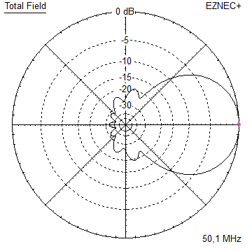
- GTV 50-7n mk2Revision of the very directive 8.6 m 50 MHz 7 ele. with bent Driver. Carefully tuned for some bandwidth and high F/R now - all without loosing on gain.
Elevation Plot
- GTV 50-8w10.7 m wide-band, still good G/T and nice F/B version of the low impedance, yet 50 ohms direct feed Low Noise Yagi with bent DE introduced in Dubus 1/2013
Elevation Plot
- GTV 50-10LT14.6 m very low noise, high G/T version of the low impedance, yet 50 ohms direct feed Low Noise Yagi with bent DE introduced in Dubus 1/2013
Elevation Plot
- YBN 50-2w
- • 70 MHz
- • 144 MHz
- • 432 MHz
• Antennas
YBN 50-5w Yagi with straight split dipole
Wide-band version ... a very wide band yet relatively Low Noise Yagi that shows least
degradation with wet elements or snow on and thus easy to reproduce parameters.
If you are looking for a Yagi suitable for worst weather condx ... this one might be it.
This shorter Yagi is designed for easest reproduction, straight split DE and direct feed
with 50 ohms at feed point.
Use a large ferrite core, coax choke 'balun' made out of several windings on a close diameter ... or a grounded Quarter Wave
line for best results. Generally it does work without any symmetrising, but a test config with a click on ferrite for Analyser
plotting or simply SWR check is appreciated.
YBN 50-5w built by Wolfgang, IN3TWX


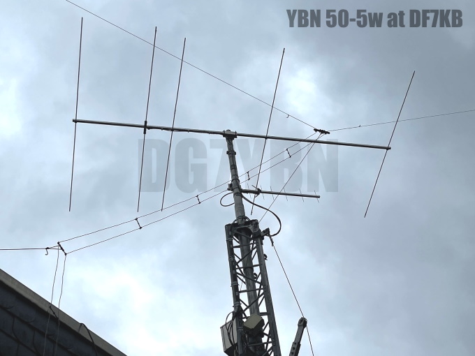
YBN 50-5w built by Wolfram, DF7KB


|
|
YBN 50-5w built by John, ZS6JON

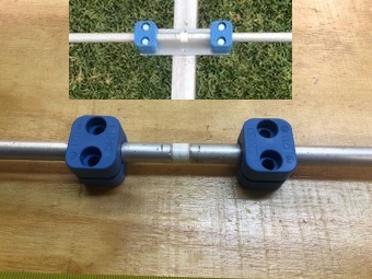
This Yagi is built with 12.7 mm = 1/2 inch elements held by Stauff clamps on a 32 x 32 mm = 1-1/4 inch boom.
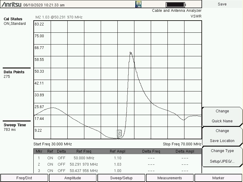
Plots with calibrated coax on an Anritsu MS2000 VNA:

                   Elem. 5/8 in + 16 mm
Gain vs. isotr. Rad.   9.9 dBi
Gain vs. Dipole        7.8 dBD
-3 dB E-plane         56.0 deg.
-3 dB H-plane         76.0 deg.
F/B                  -25.5 dB
F/R                  -20.3 dB
Impedance               50 ohms
VSWR Band Width     1.01:1 *
Mechan. Length        4380 mm
Electr. Length        0.74 λ

Stacking Dist. h-pol.
top-to-bottom         4.86 m = 15.94 ft
side-by-side          6.37 m = 20.91 ft

*) as in VE7BQH G/T table = at 50.50 MHz
Geometry
Elements Ø12 mm:
Elements Ø5/8 inch and 16 mm:
Elements Ø5/8 inch and 16 mm Elements - On Boom - high insulators (Stauff)>
		Refl	  DE	  D1	  D2	   D3
Pos.		   0	 912	1284    2600	 4380
Boom 30x30mm	2954	2936	2746	2640	 2450
Elements 1/2 inch:

Elements Ø1/2 inch - On Boom - high insulators (Stauff)
		Refl	  DE	  D1	  D2	   D3
Pos.		   0	 912	1284    2600	 4380
Boom 30x30mm	2954	2939	2759	2656.8	 2472
Table: YBN 50-5w, 12.7 mm or 1/2 inch elements on a 1-1/4 inch square boom:
"Ready to saw and drill" data for elements on boom with BC acc. DG7YBN for Stauff Clamps:
|
Boom shape: square Boom: 1-1/4 inch Offset rear: 50 mm Offset front: 50 mm |
Stauff Clamps 2-12.7-PP |

Note: This includes a "Segmentation Density Correction" (SBC) of 0 mm
There is NO SBC since this Yagi is designed with low segmentation. Add just a few millimeters
of BC depending on mounting method of elements or insulators used.
DX-Expeditoners Wire Geometry
Make your Yagi on the fly out of wooden laces and thin aluminuim rods or blank or stranded wire.

| Attenzione!
There is no wire insulations influence taken into account here yet! It is clear that typical stranded wire insulation from PVC introduces a dielectrical constant to the Yagi wires. Depending on the actual plastic this number is expected to be around 3 (1 MHz) and depending on frequency. Its thickness depends on the actual make of wire. Both will introduce a noticable velocity factor on our wires. So that using insulated wires the actual wire lengths must be shortened by several 10 mm! |

|
An uninsulated wire might be the way to go ... instead of messing with unclear insulation dielectra and contributing around 0.1 dB for heating up the insulation plastic. |
• Diam. 4 mm / AWG 6 uninsulated wire => 9.83 dBi still
• Stranded wire: diam. 2 mm / AWG 12=> 9.74 dBi still
Attenzione: for a PVC wire insulation a full scaling needs to be done, it is not sufficient to just cut a fixed number of millimeters
Not insulated wire
For a PVC wire insulation with a thickness of 0.5 mm I find a shortening effect of 70 mm coarsely
• Stranded wire: diam. 1.38 mm = 1.5 mm2 / AWG 16 uninsulated wire => 9.66 dBi still; Attentione: D1's position has changed
Pattern and VSWR Plots
Elevation and Azimuth plot at 50.1 MHz


RL and SWR plot - simulated / 49.0 - 51.0 MHz

Elements 12 mm versions Return Loss
Downloads
EZNEC file of this Yagi with 5/8" elements
EZNEC file of this Yagi as wire Yagi with 1.5mm2 ele.
Stacking
Elevation plot of 5 over 5 at 50.1 MHz using DL6WU stacking distances
Stacking Dist.    DL6WU Formula
H-plane               4.86 m
E-plane               6.37 m
Gain vs. isotr. Rad.  12.7 dBi
Gain vs. Dipole       10.6 dBD
-3 dB H-plane         56.0 deg.
-3 dB E-plane         33.0 deg.
F/B                  -19.1 dB
F/R                  -19.1 dB
73, Hartmut, DG7YBN