-
• Main Page
- • Home
• Antennas - • 40 MHz
- • 50 MHz
- YBN 50-2wA 1.2 m 50 MHz 2 ele. with split Dipole for direct 50 ohms feed to be very uncritical for home building. A wideband version with hugh bandwidth.
A project for an afternoon ...
Antenna View
- YBN 50-5wrc vsA 4 m 50 MHz 5 ele. with hairpin match and split Dipole to be very uncritical for home building.
Elevation Plot
- YBN 50-5wA 4.4 m 50 MHz 5 ele. derived from the 2 m 5 ele with split Dipole to be very uncritical for home building. A wideband version with hugh bandwidth and yet high F/B.
Elevation Plot
- YBN 50-7mzcA 7.96 m 50 MHz 7 ele. with hairpin match and split Dipole to be very uncritical for home building.
Elevation Plot
- YBN 50-9mA 13 m 50 MHz 9 ele. derived from the 2 m GTV 2-9m but with split Dipole to be very uncritical for home building.
Elevation Plot
- GTV 50-3wA 1.8 m 50 MHz 3 ele. Yagi. A wideband version with much bandwidth and yet relatively high F/B for its size
Elevation Plot
- GTV 50-6mA 6.8 m 50 MHz 6 ele. Yagi with very high F/B for its size
Elevation Plot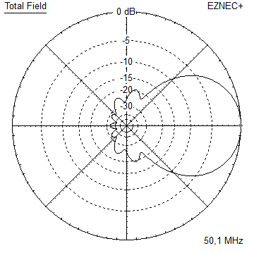
- GTV 50-7n mk2Revision of the very directive 8.6 m 50 MHz 7 ele. with bent Driver. Carefully tuned for some bandwidth and high F/R now - all without loosing on gain.
Elevation Plot
- GTV 50-8w10.7 m wide-band, still good G/T and nice F/B version of the low impedance, yet 50 ohms direct feed Low Noise Yagi with bent DE introduced in Dubus 1/2013
Elevation Plot
- GTV 50-10LT14.6 m very low noise, high G/T version of the low impedance, yet 50 ohms direct feed Low Noise Yagi with bent DE introduced in Dubus 1/2013
Elevation Plot
- YBN 50-2w
- • 70 MHz
- • 144 MHz
- • 432 MHz
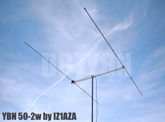
YBN 50-2w: Simple, easy to produce 2 Ele. Yagi
This little Yagi is as much bandwidth as can be. A forgiving and easy to build alternative to the HB9CV.
Take a view at the stacking section: 4 x 2 elem. vertical produce 13.5 dBi at a HPBW of 71 degr.
You will not miss any ES opening with this broad and flat main beam!
It does not have the HB9CV's famous F/B ratio but is much easier to build, no phasing lines, no capacitor ...
Nothing to protect from rain and snow. When you ar portable with a little antenna and little rig anyway
a high F/B does not help much. And note that the HB9CV's true gain is around 4.15 ... 4.2 dBD. No more then that.
YBN 50-2 w by IZ1AZA
Details see

Performance Data
Gain vs. isotr. Rad.   6.4 dBi
Gain vs. Dipole        4.3 dBD
-3 dB H-plane        134.8 deg.
-3 dB E-plane         69.8 deg.
F/B                   -9.3 dB
F/R                   -6.3 dB
Impedance               50 ohms
Mechan. Length        1178 mm
Electr. Length        0.20 λ

Stacking Dist. h-pol.
top-to-bottom          3.24 m or 10.6 ft
side-by-side           5.22 m or 17.1 ft
Geometry
        Pos.     Length
                 in NEC

Refl.     0       2936
DE     1178       2736
Ele.      Ø       12 mm

BC needs to be added according element holders & boom diameter chosen
Geometry

On-Boom-Holders: see here
The Driver Dipoles diameter is 12 mm for all examples.
Use EZNEC's Auto-Segmentation at 50.15 MHz.
Who has been looking at this Yagi?
Pattern and VSWR Plots
Elevation and Azimuth plot

RL and SWR plot

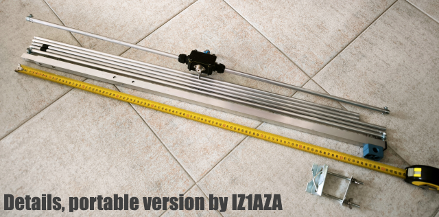
Tapered Builds
In some regions a sufficient length of 12 mm or 3/8" tube may be hard to purchase.
So I show how to build a tapered version here. Which same time offers an easy ability
to trim to frequency by adjusting the pushed in lenghts of the outer tubes.

geometry shown in the sketch below


Details of IZ1AZA's portable version build:
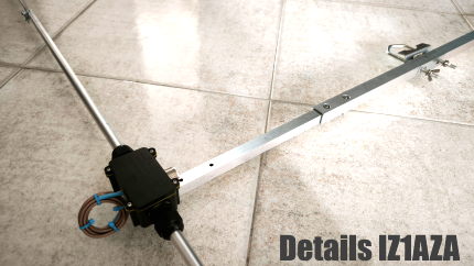
Feeding the coax

and an N-flange-bushing on the to-ground side. For any very simple build you might do
without the ferrite core even as long as the QW-line is grounded in a low impedant way.
Which is to use a broad, flat bracket.
How to derive length (a)?
Wavelength is 5.978 m for 50.15 MHz. Length (a) is (5.978 m / 4) x v-factor.
Minus a few millimeters for the frequency depending v-factor of the insulation plastic.
Which usually is around plus 3 ... 4 percent at 50 MHz with means multiplication by 0.96.
For a PE coax that means (a) = 5.978 mm x 0.25 x 0.66 x 0.96 = 947 mm
For a foam coax that means (a) = 5.978 mm x 0.25 x 0.82 x 0.96 = 1176 mm
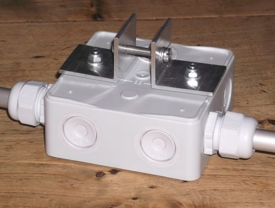
Dipole Box
Box is a 'Spelsberg Abox 040 Nautic, Industrial Quality acc. EN 606 70, IP65, free of halogene,
weatherproof, comes with cable gland size M20 spare holes' - 93 x 93 x 55 mm

Inside Closeup: Tube ends carry 2 slots, mid insulator is a glass fibre reinforced plastic rod Ø 11,7 mm by LA4ZH
(www.eidolon.no), 2 hose clamps fastening the mid rod plus connecting stripes made from 1 mm copper.

Boom face side: Making use of the 2 forseen fastening holes and two self cut brackets 35 x 30 mm to
mount to boom on a broad supporting area using a screw M5 x 30 (boom 20 x 30 mm)
Downloads
EZNEC file of this Yagi with Straight Split DE