Modified DL7KM Beam for the 70cm Band with Double Quad Driven Element
The DL7KM beam has a fan community on its own. Among those are a number of contesters.
I became curious about what would be in this design.
How good is the DL7KM Beam?
• R. Bertelsmeier, DJ9BV: "Gain and Performance Data of 432 MHz Antennas (Leistungsdaten von 432 MHz Antennen)", Dubus 1989: Rainer attested the 70 cm version a forward gain of 9.75 dBD (11.90 dBi) only. But that is due to "badly mistuned directors, because of wrong scaling from the 2 m version. Cutting all elements will increase gain to 12.0 dBD, which is also low for this size."
See details and whole theory on the website revising the 2 m band version
The outcome of the simulation of the 2 m Band version made me think about a redesign for the 2 m and 70 cm band immediately.
About the Design modification
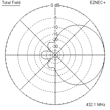
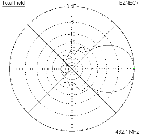
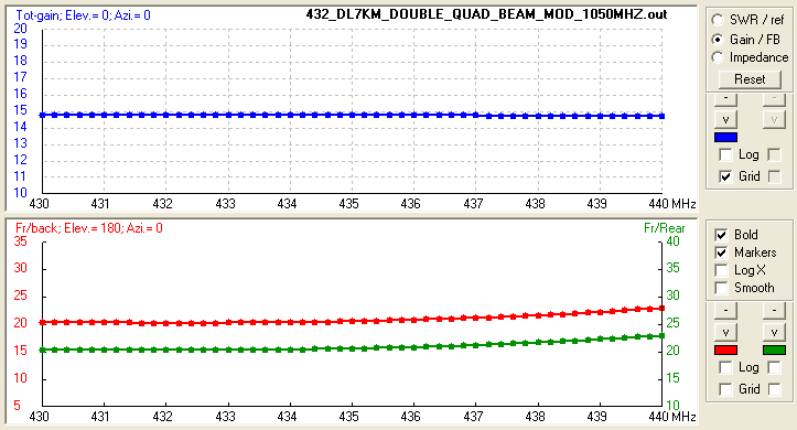
After setting up a NEC model and looking at the output with barely 12 dBD I decided to do a redesign that a build of the original beam can be adapted to. The outcome covers the full 70 cm band with a very low SWR and delivers consistant gain over 431 to 435 MHz dropping by only 0.1 dB towards 440 MHz. Same time it delivers at least 1 dB more gain and much less Antenna Temperature thanks to a much cleaner pattern.
Modified design with small inner structure

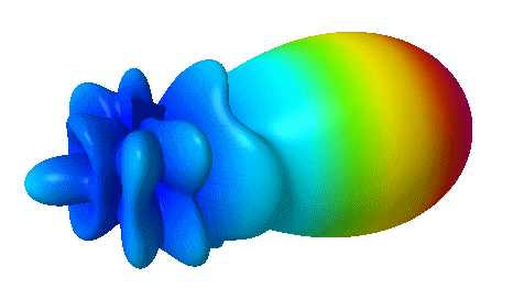
I elemininated one element from the wave guiding structure each, spread the remaining ones more sensibly over the boom length, modified their lengths, moved the reflectors closer in, and added three inner directing elements - which play a major role in tying up the beams pattern.
Performance Data of original and modified Design
                      Mod. YBN
Gain vs. isotr. Rad.  14.8 dBi with corrected AG
Gain vs. Dipole       12.6 dBD
-3 dB E-plane         33.3 deg.
-3 dB H-plane         37.4 deg.
F/B                  -20.3 dB
F/R                  -20.3 dB
Impedance               50 ohms
VSWR Band Width      <1.1:1 on complete band
Mechan. Length        1314 mm
Electr. Length        1.89 λ
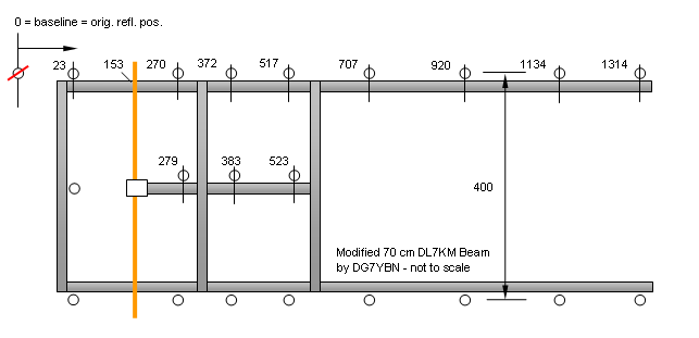
Geometry of the modified design
NEC wires segmented at 1050 MHz; feedpoint = zero on z axis
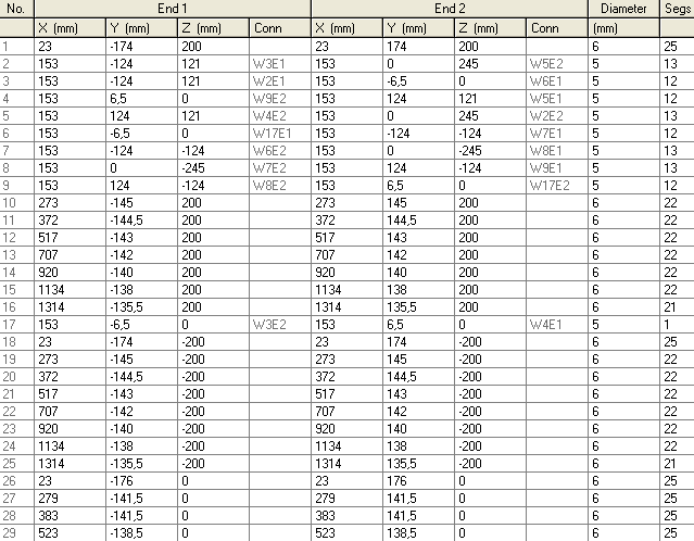
No BC, no SBC given yet. Boomless numbers as used in the NEC file only.
Positions zero is counting from original reflectos position as "0" on. The new reflectors are moved up front by 23 mm against their original position. Built DL7KM Beams can be adapted to the modification; the double booms spacing is with 400 mm similar to the original design.
For the given below measures elements are of Ø 6 mm, Quad loops are Ø 5 mm. Due to the rectangular, loop style driver I suggest no SBC here. The common BC must meet the way your elements shall be fastened. Find BC numbers on my BC-page
8 mm elements - upper and lower boom
       Refl.    DE       D1       D2       D3       D4       D5      D6      D7
Pos.   23       153      273      372      517      707      920     1134    1314 mm
Lgth.  348       -       290      289      286      284      280     276     271  mm

8 mm elements - short center boom
       Refl.    DE       D1       D2       D3
Pos.   23       153      279      383      523 mm
Lgth.  352       -       283      283      277  mm
Note: element lengths for Ø 6 mm almost fit 1/4" too, subtract -0.5 mm for the Imperial measure.
The Double Quads wire diameter is 5 mm. The loops side lengths are 175.4 mm in NEC - which is mid wire - pus half wire thickness gives us outer side lengths of 177.9 mm each, a total height of 495 mm and a space of 10 ... 12 mm at the centered feedpoint.
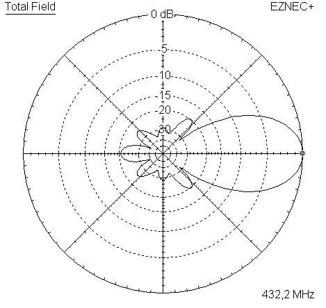
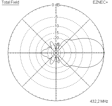
Pattern and VSWR Plots of the modified design
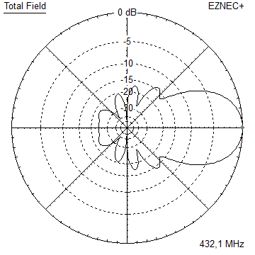
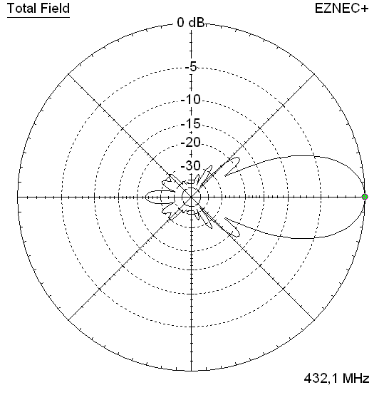
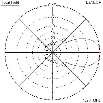
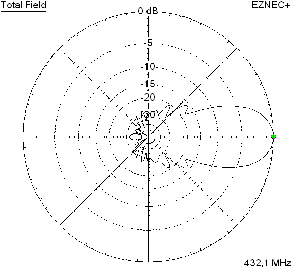
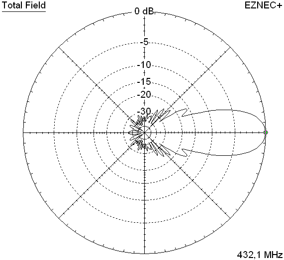
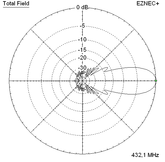
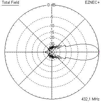
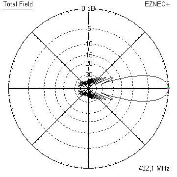
Elevation and Azimuth plot on 432.2 MHz
RL and SWR plot - simulated

Gain, F/B and F/R plot - simulated
Downloads
EZNEC file of the modified DL7KM Beam
Stacking the modified DL7KM Beam
Stacking Dist. DL6WU Formula
top-to-bottom (H-plane) 1.21 m or 3.97 ft ✶
side-by-side (E-plane) 1.08 m or 3.55 ft✶
(✶) = for center of antennas ie. in the middle point between the booms
A 4 bay of modified DL7KM Beams at distances per DL6WU formula, gain = 20.7 dBi or 18.6 dBD
Note the unusual appearance of the stack. With the pattern being more wide in azimuth pattern the
used to view of a stacked Yagi bay is like reversed or tilted by 90 degrees here.
Explanation: Due to showing wider elevation patterns half power beam width (HPBW) angle than azimuth HPBW the ordinary 'single boom' Yagi is stacked with larger width than height. While the DL7KM beam is a '2 layer' stacked array in itself already. And the modified DL7KM beam shows 3 layers that bundle the pattern in elevation already. Hence we find a 'reverse' ratio of stacking width and height against what we know as common appearence of stacked single layer Yagis.
Stacking Scheme

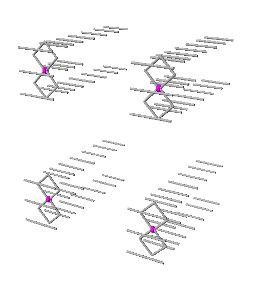
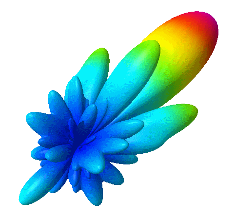
And a screenshot from the analysis of the Far Field Table with TANT by YT1NT
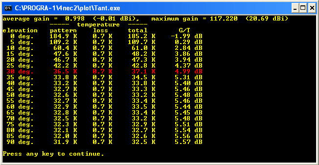
Not too bad. Comparing with entries in the 432 MHz VE7BQH G/T Table we find that it takes a 4 bay of narrow band width 11 ele. Yagis of 2.8 wl eletrical length or 1.9 m boom to beat this result. And that will only happen in the dry. With the very wide band width of the mod. DL7KM Beam you can be pretty certain to obtain this performance uneffected even with completely wet antennas. But ... we need to run an Average Gain Correction on this, as with real losses the AG is at 0.998 or 99.8 percent radiated power found in the pattern against fed in power. So that results will have to be corrected downwards by a few 10th of dBs.
73, Hartmut, DG7YBN

